Trimble Business Center: Tips and Tricks

Trimble Business Center: Tips and Tricks

When you are learning software, there are two approaches; menu driven and process driven. Software developers write commands so that understanding software revolves around the command(s) that fit the need. My approach is to find the shortest and straightest line to the finish. Processing data, for instance, can take 15 to 30 commands. I want the most direct path to the result. This often varies widely depending on factory or dealer training.

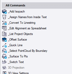
I will highlight some of the commands that I use for data prep that can make things go smoother. This is a good way to verify if you can streamline your process.
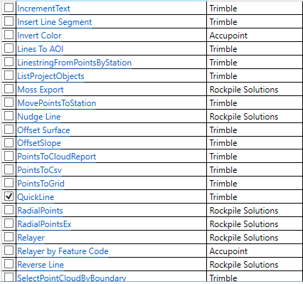
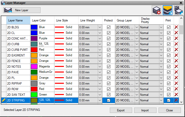
CAD Elements

The first thing I like to do is get what I want on the correct layer group. This also brings up the discussion of how to build a surface. Do you take some layers and create a surface, or do you go through categorizing layers to let TBC create the surface? I have had many discussions, regarding this subject. Taking layers to create a surface doesn’t take a lot of additional time, and when the client asks for a takeoff, it becomes a no brainer. My world is mostly solving problems and not production. I will create a quick surface to try an idea or solve an issue. My thought is to play it by the numbers and check off the layers you want to be included in the surface.

To make this easier, I will name the layers what they are and dispense with the engineer’s goofy wording. Just go to the layer manager and type in a new name.

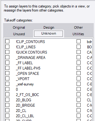
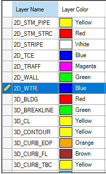
These layer names all now have been changed to CAD Standards. Having the same name used in every file is something everyone should do.

Where are we

At this point I have renamed the layers that have what I want for my model and linework. From there I have categorized them according to the places they need to be. Be assured when I get to this point, the list is dynamic. I will move things in and out of the groups to make things work better. This is where some of you may be thinking this process is not as good as including a few selected layers into a surface. I have done time and motion studies and it becomes a coin toss, but as I stated earlier, it sets you up well for a takeoff and changes to the site as the job progresses.

3D Elements

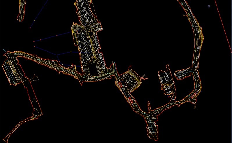
A surface is composed of three basic things: 2D lines, 3D lines and points. They are linked together to form a TIN, Triangulated Irregular Network. Choosing what goes into the mix is the rub. I want detail but not so much to clog the screen and drive me crazy when the time comes to fix things. In the old days, we used to worry about large surface files. They would slow down machines and make things jumpy. Now the control boxes create page files that are no longer an issue. Data collectors can still be a victim here, so it is wise to be aware of the surface file size.

Linestrings

Love or hate the name, we live and die by linestrings in TBC. When creating lines for a surface, I want to make sure all the lines I am dealing with are linestrings. Luckily, there is a TML (Transport Mapping Layer) for that, and you need to use it for the layers that are going to be a part of a surface.

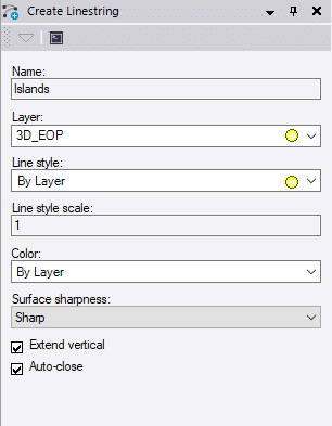
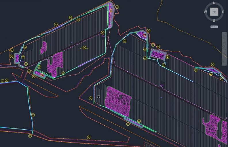
Use the details that can be added to a linestring to make it stand out. Go beyond the layer name. You can see here I have named the lines that will be my islands. They reside on the edge of pavement layer, but I can select them by name if I want to do something with them later. Line style is a bit of a problem. TBC is not good with handling a lot of different line styles, so we default to “show all lines as solid” in the icons at the bottom of the screen.

I will sometimes delete the layers that I do not need or change their line type to solid to make graphics happy. One of the major threads you see in this is the adaptation of the files and work you do to create the outcome you need. Therein lies the difference in training styles – I need to get this out the door, not explore the merits of the new useless command.
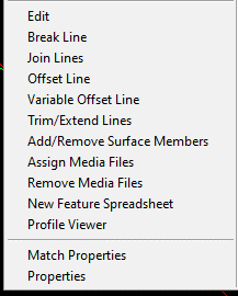
Linestring Tips

Here are some tips that make things easier with linestrings.

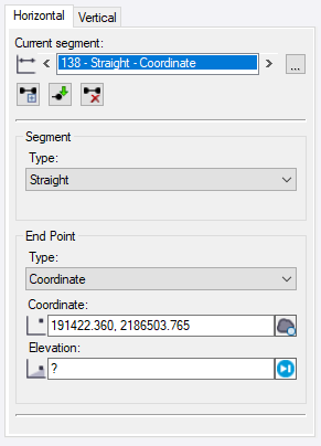
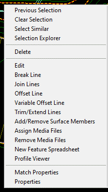
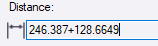
  • Right click is your friend. Go into the coordinate box of edit a linestring and right click. A lot of options for COGO (Coordinate Geometry) come up.
  • You can do math inside an instruction. In this example I did a bearing/distance segment. The bearing is entered but I need to add two distances. I am lazy so I just do the addition in the command line:
  • Arcs are easy to do with a lot of options including smooth curves and best fit arcs. There are also detailed COGO routines for curve functions that require exact information. The quick arc to clean up an area is a big help.
  • The Browse feature lets you look at the history of a line and drill down to fix issues.
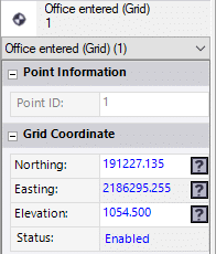
  • Linestrings have two separate and editable attributes, horizontal and vertical. You can change the way a line looks on the screen and keep the vertical elevation points you held when entering them from the plans.
  • Elevations do not need to be numbers. You can use deltas or percent slope.
  • The toggle segments button in edit linestring will make everything smooth curves.

Point Density for Surfaces

When I build a surface, I like to enter the least amount of information possible. Here is a typical scenario:

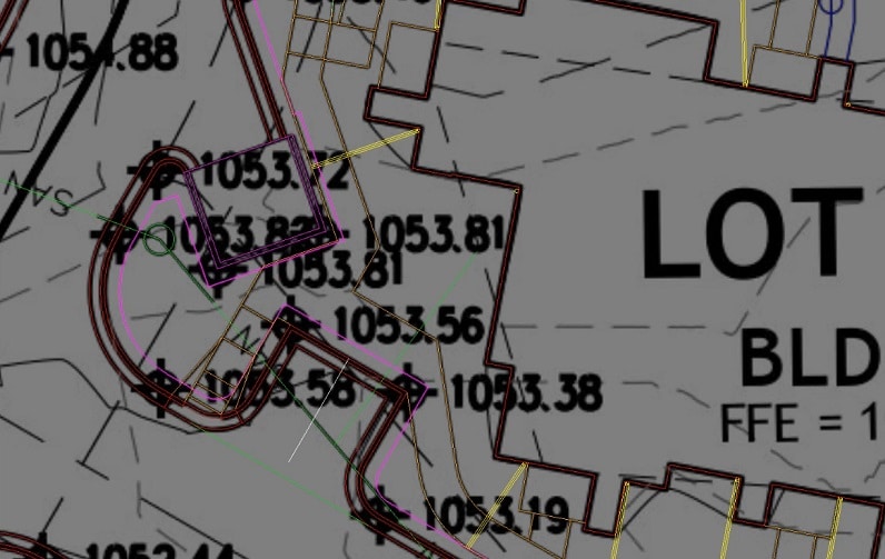
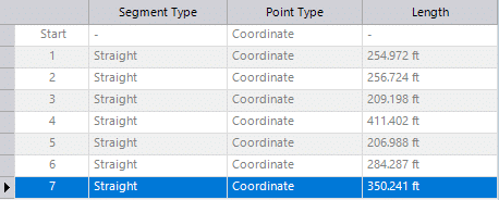
  • Enter elevations of contours to get things started.
  • Elevate curb points to match the plans.
  • Add points that look like they are necessary.

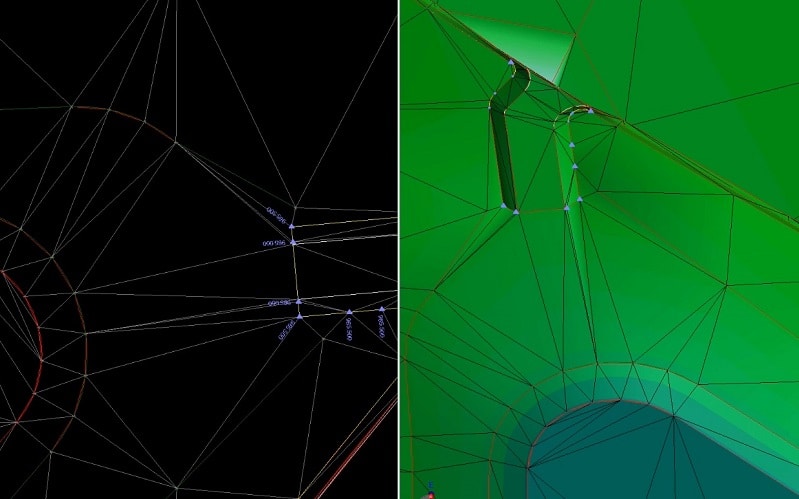
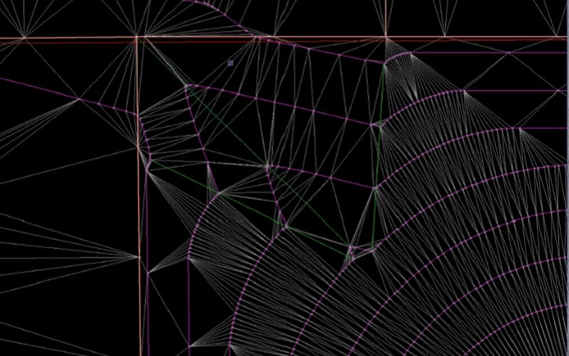
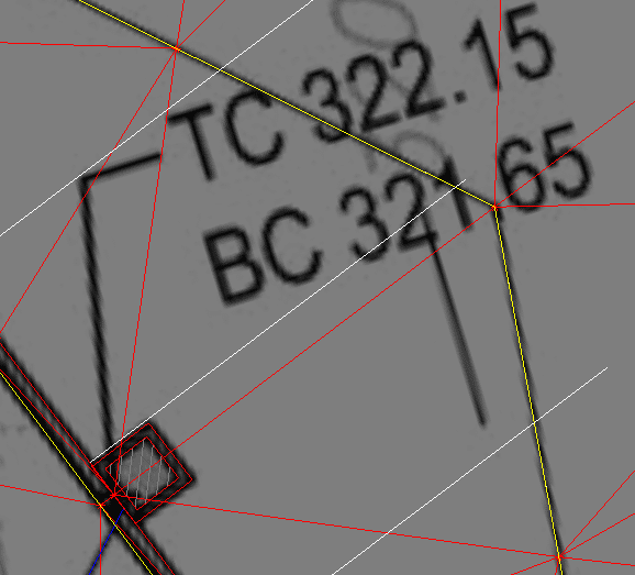
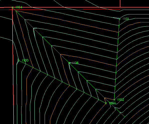
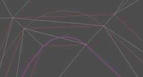
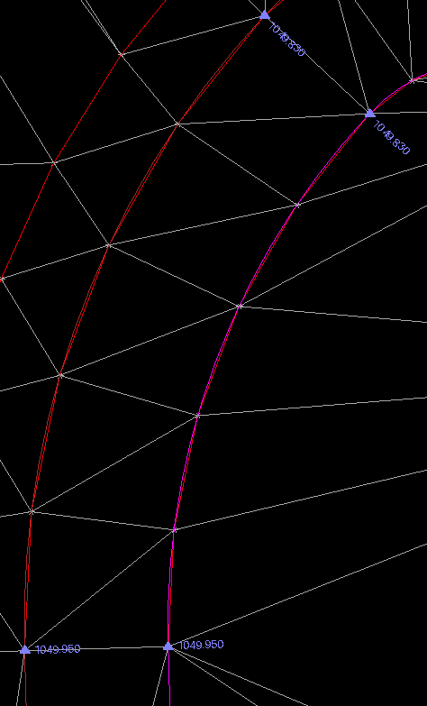
At this stage of the game, we have the minimal information to build a surface. Note that the arcs have become segmented because an arc cannot be elevated. This creates a mess, but I want you to see the process of building a surface.


Here we see the straight line that crosses the arc for the curb line. I have adjusted the settings to not create breaklines in the arc, but I see the elevations and can verify I am not out of tolerance anywhere.

When I am satisfied with the basics, I will let the program do two things.

  1. Add breaklines to the arcs and clean up the curves.
  2. Insert points along straight segments at the interval I want. For small sites I will go out to 10 feet. As the area gets bigger, I will set it to 20 feet as to not choke the controller.

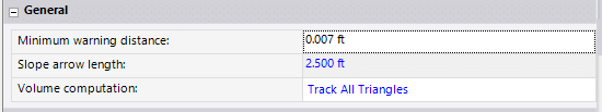
These changes can be made on the fly and adjusted for results. You will find them in Settings/Surface/Computations.

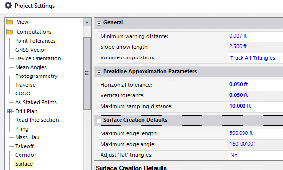
These are the settings I will use for this project. A half a tenth on horizontal and vertical node placement and no more than 10 feet between points along a straight line.

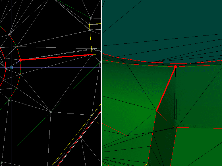
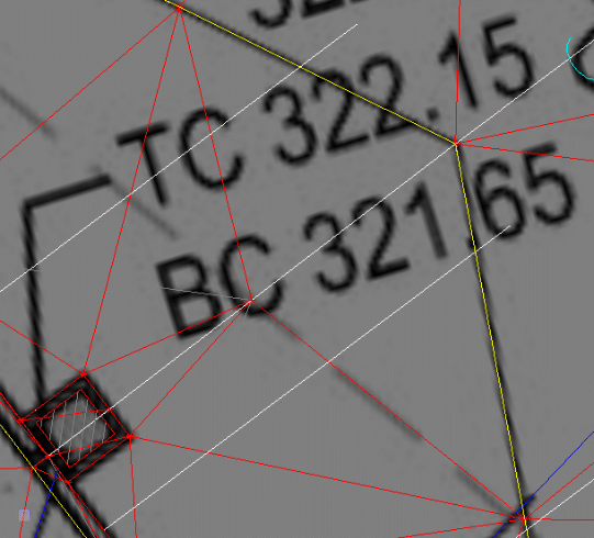
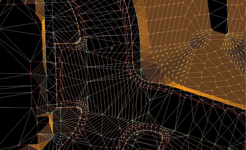
Here is that previous train wreck fixed with updated settings.

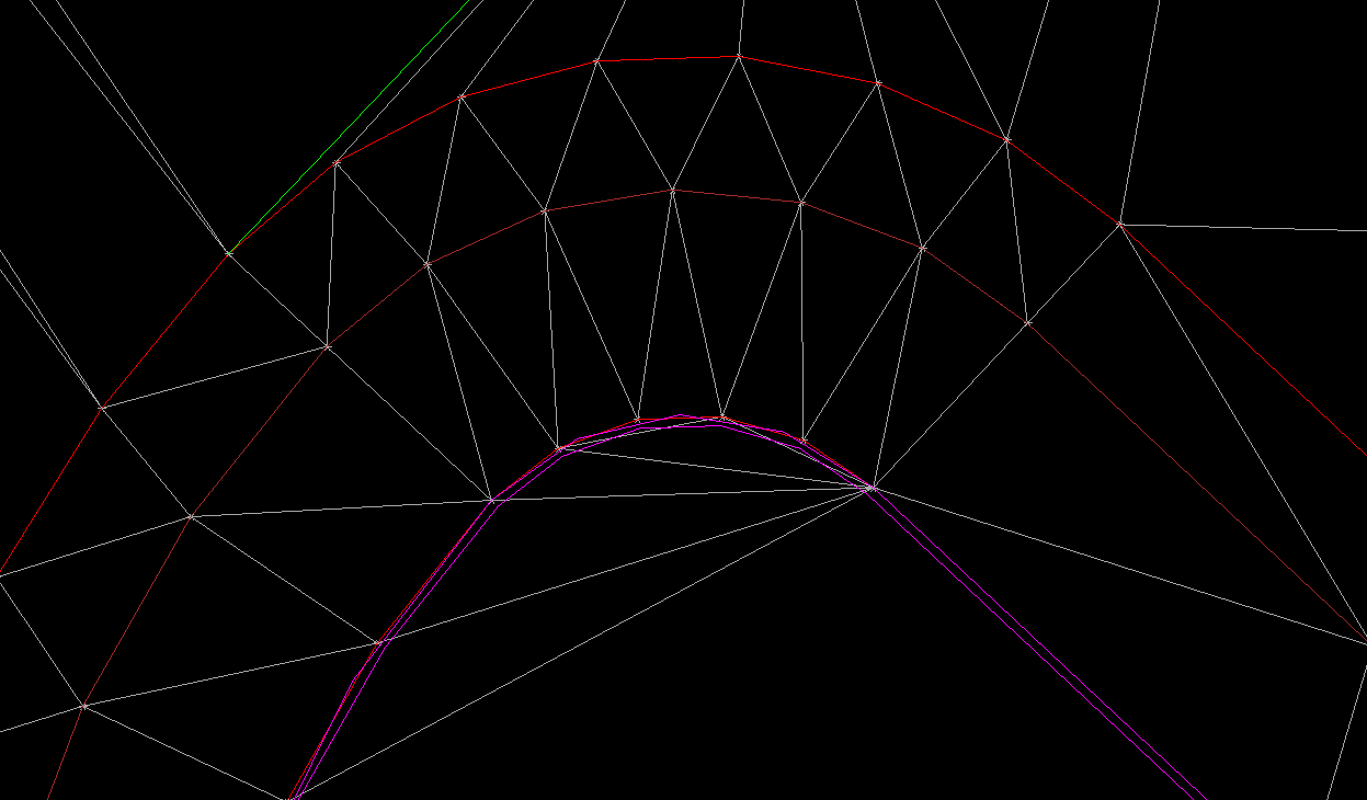
I do not always swing point placement settings this far out when building a model. There are times when you want to see the information you inserted and see where the problems are. The fact is that any interpolation of the elevations is a direct result of what you did in the first place so the errors can be fixed because you did them. Go back to the part that does not look good and get it correct.

The big thing to remember here is the linestring that needs fixing only has the elevation points you entered so the repair is easier.
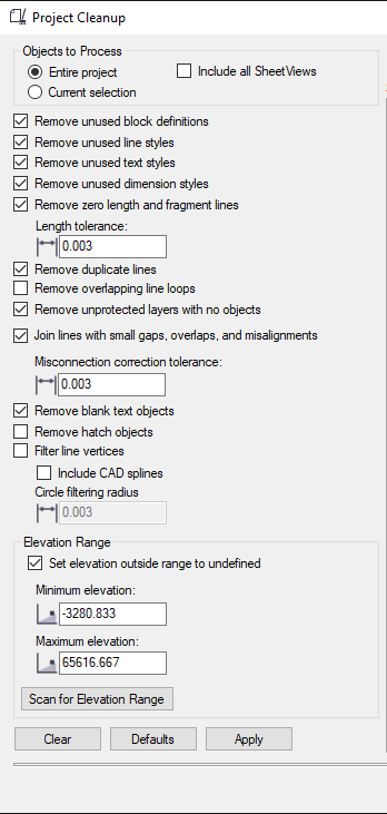
If you look at the elevations called out on this image there are just two typed elevations with interpolated points between. You can also approach a surface this way. When there is a lot going on, this can get quite busy with elevations and make it hard to see and fix.

Surface Tools

I love when I first get a surface made. Often, things are looking good but there is always room for improvement. Here are a couple things I do to check quality.
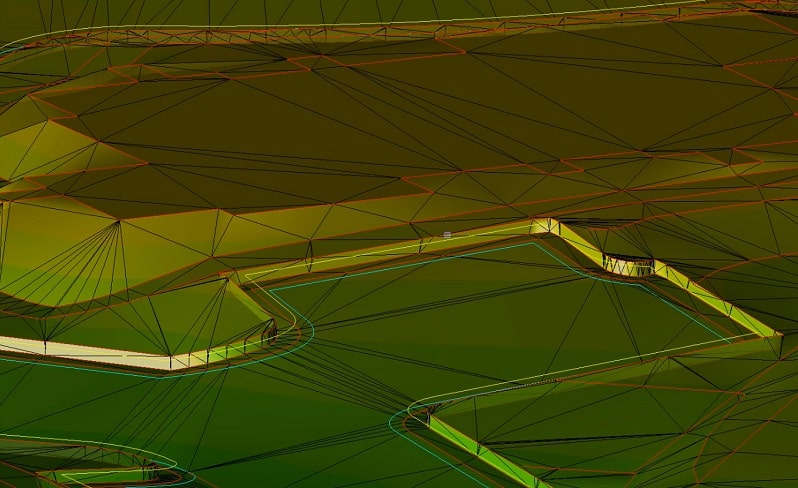
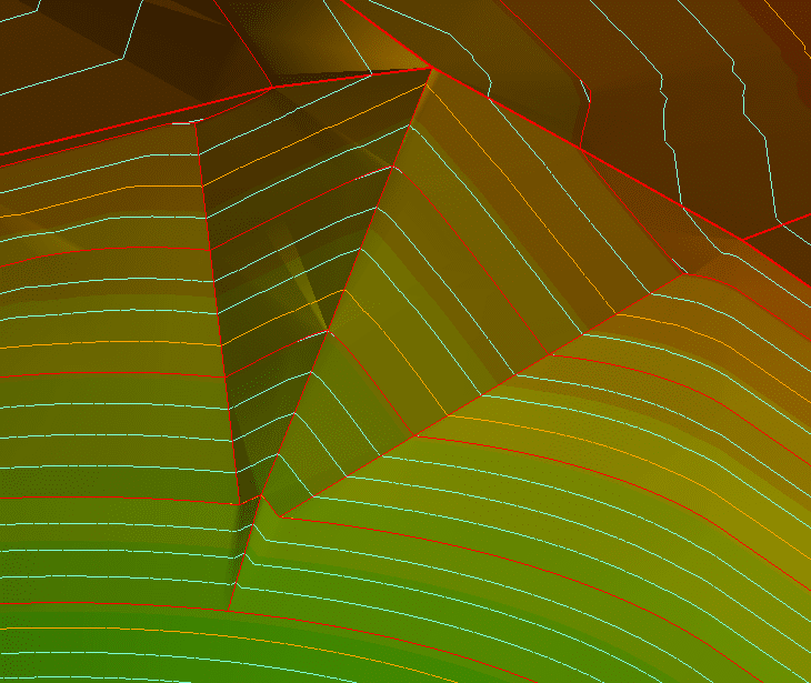
Contours

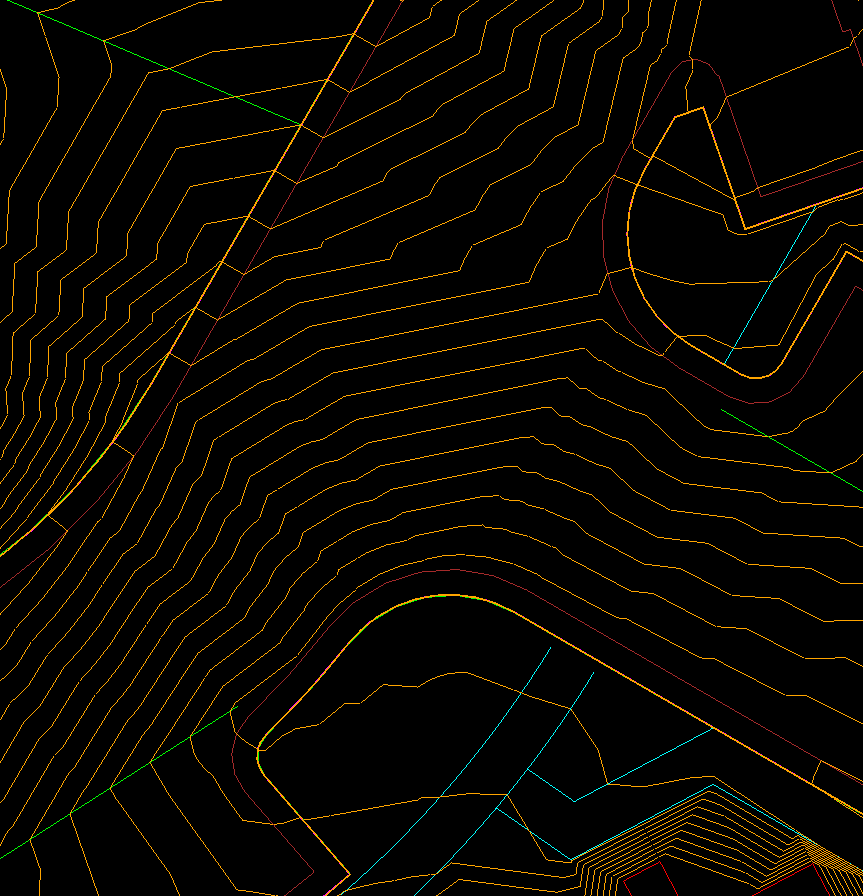
I can use contours to get a rough idea of how things look. To really get detailed, I will make the interval a tenth of a foot. No need for multiple colors, labels, or layers. You can get a good idea where to focus your energy for repairs. The image above shows a clean movement of water in this intersection. It took some work to get there and it paid off. The paving will look nice and it will move to drain correctly. Always go back to one-foot intervals after you are done for a basic sanity check. Don’t be alarmed if your contours do not match the plans exactly. Any tweaking you have done will alter the location of the one-foot lines.
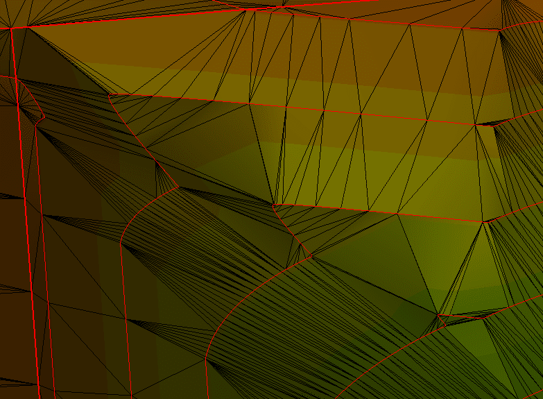
Breaklines

A breakline is nothing special. It is just another name for a 3D line. We call them that because during the days of point surveys we forced a break along a line in the surface, usually at the top and toe of slopes. The name stuck and now they are used to improve a surface’s performance.

I like to use the plan and 3D views to get instant feedback. Make sure the surface rebuild method is set to auto. You will get a chance to try different ideas. As you do more of this there will be clear winning ideas for breakline placement. Pay attention to your process to reduce lines that do not help.


3D Data: Looking Beyond Machine Control

3D Data: Looking Beyond Machine Control

For many years, our business has been centered on the production of 3D data modeling for machine control. This is the low hanging fruit of a civil site. High dollar paving, building pads, and retentions are easier to do and higher quality with machine control. Fast forward to current times.

Many civil sites are being completed with machine control. The use of machine control on the job site has become a reality, to the point that contractors have started to look beyond their current use and possibilities. As many of you know, I have long been a proponent of leveraging data for a job site. I have worked with many of our clients on how to better use the data they have in their hands and drastically improve production and profits.

I will go over several ideas that are good next steps for users of 3D site data. They are in no particular order of profitability. Any site may or may not be able to use these processes. Not to worry, I will back up the explanations with a video to better explain these ideas.

2D and 3D Points

Considered the domain of survey, a point has specific and relative information. I’ll use points for laying out a curb arc as an example. 3D points for the PC and PT of a curb arc give us the location and elevations of that curb run. We know the slope between the points and paving elevation is an easy calculation. Next, we add the arc center as a 2D point. Now there is a pivot to swing an arc for form or string line layout. Increasing the power of points, we offset the curb line to allow the field to set string line for a curb machine.

Site Layout

Using earth moving equipment to get the dirt right is a huge time saver. We also advocate the use of positioning technology for more than grading.

Electrical

It started with light pole bases and quickly escalated from there. We now regularly provide data as 2D or 3D points for the following.

  • SES pads. The job has been checked so we are good with drainage and elevations on the site. The electrical service slab is easy to calculate from available regulations.
  • Common area in-ground power. Many plaza shopping centers have electrical connections for decorations and kiosks. Knowing the 3D location of the connections allows electricians to easily set them right the first time.
  • Common area hardscape. Everything from playground equipment to benches, these additions need some type of base and connection. It is best to know what can be accomplished while access is easy and save re-digging to set later.

Utilities

We have been providing utility layout for years. We show points 10 feet apart on the flowline for pipe with horizontal offsets if needed. Structures are marked as well. The advent of successful machine control for excavators has allowed us to provide a trench network so the operator can dig trenches correctly the first time.

Other utility details that can benefit from information provided in the data are:

  • FES’s, wing walls and valley gutters. These concrete structures are better done in rough grade, but many contractors wait until near the end of construction and field fit. With a correctly prepared model there is enough confidence to build these when it’s convenient to the crew.
  • Water lines are usually specified as a minimum depth below finish grade. We build the line in the data so crews can place it at any time and not make a mess of the just completed grading with required wheel trenching.
  • Subdivisions have utility connections for each lot which we handle one of two ways.
    • We can layout all the laterals and they are placed according to plan. When it’s time to make the connection, the rover is used to find the location of the pipe.
    • When the utilities are not well defined or connections have to move, as-built shots are taken and we update the model for easy use in the future.

As-Builts

Taking shots along the way provide an ongoing record of what is being done. This helps to establish production rates as well as the basis for future submittal drawings. Here is one way to bring this into your workflow.

  • I call this the “daily topo walk around.” While reviewing the work being done on a site, the superintendent has a rover and takes ground topo shots as well as items being put in the ground. In a perfect world, points would be coded but that is not critical.
  • We often are asked to convert the walk around topos into as-builts or progress takeoffs. With the model on the screen overlaid to the topo points, we can usually figure out what the shots represent.
  • Utilities are the biggest winner with as-built points. Before covering, if the top of pipe is measured, those are later converted to as-built drawings we put together for closing submittals. Many contractors have an issue with this, and we get it. It’s one thing to get the points but now the office needs to do full blown CAD drafting and plotting.

I will help to tie these ideas together in a video linked HERE. Please don’t hesitate to ask any questions you may have regarding these or other issues.

Update May 2020

All the things I discussed above pale in comparison to the big picture of data we strive for. All these elements are time savers and money makers, but they lead to the overarching point that data must be moved efficiently and used by everyone to be successful.

Let me follow some enhanced data through the process so you can see what needs to happen. In this example, I will work with the installation of a deceleration lane and entry to a commercial site.

Office

  • Plans are reviewed and data built to existing grades shown on the plans.
  • Model works well with the information we have.
  • I note the entry and ask the field to get measurements of the paving at the sawcut line.

Field

  • Site is set up and work starts.
  • When appropriate, the field shoots paving elevations for the entry.
  • The field notices the elevations are not matching with what they have on their model. The road is higher than what the model says it is supposed to be.
  • Shots are sent to the office.

Office

  • I take the shots from the field and compare to the plan version of the existing conditions.
  • I make the adjustments to the surface and entry elevations to line up with what is there. I do not want to design the entry, but I want to present a solution to the engineer if possible. Never ask a question you do not know the answer to.
  • Information is sent to the engineer for collaboration.
  • Engineer approves the changes. Always make sure you get this in writing such as email. Phone approvals will come back to bite you, don’t ask how I know.
  • Model is updated and sent to the field.

As I have outlined here, the depth of 3D data is realized only when it is shared and leveraged by all parties. Share the information with engineers and surveyors to improve the quality and speed of the project. Everybody wins when you give out good data.

UPDATE: Chasing Perfection on Civil Sites

UPDATE: Chasing Perfection on Civil Sites

Our previous article on chasing perfection on civil sites covered the balance between a perfect model on screen and a well-priced practical job that performs well. In this article, we further explain the details that we touched on as well as additional tips to use to make a job run smoother.

If you take the approach of creating a ton of data for a jobsite, it takes too much time and will confuse a field user that may not be aware of the enhancements made to their job. Some of our clients have used the following ideas at one time or another but not all of them at once. Another consideration is phasing and machine type.

There are two important things to consider before deciding to use information above a basic model; the benefit of the data in the field and the cost to produce it. Also confirm the desire and ability of field crews to wisely spend that additional work and money. Regarding enhanced data, I can work with two different crews from the same company and get buy in from only one. Culture sometimes is not companywide. You need a champion to grab a new idea and leverage it for real success.

START AT THE BEGINNING

We need to establish a point of departure for my ideas. At the bare minimum, you should present to the field a correct finished surface model showing areas that are going to be worked with a blade. Nothing fancy, but a faithful representation of the intent of the job. I use the word intent with an explanation. It is the intention of all involved to have a good looking well performing site. If the plans don’t reflect it, you are the last line of sanity before something incorrect gets put in the ground.

This basic model is what most companies who do in-house data provide. Office staff are just too fractured to spend too much time on any one job. I know, I’ve been there. When field crews get comfortable with a basic model, they usually want more information to boost productivity.

We will increase data information with a new user as their comfort level increases. The real trick is providing what makes the most impact for boosting productivity.

ENHANCED DATA OPTIONS

I like to produce the most bang for our client’s buck, and the following concepts can get you there. I will go through these concepts in a video as well. A few minutes of screen time can say a lot.

LINEAR FEATURES

Lines can be either 2D or 3D. Adding the third dimension may work okay for some data collectors but not machines. A 2D line with a surface reference beneath it seems to work in most cases. This will save on data prep time. The exception to this would be for a curb alignment in a parking lot. The top of a curb is only six (6) inches wide; to the inside of the line the elevation drops quickly to the gutter. We will often provide a top back of curb elevation surface that’s three (3) feet wide so the elevation is easy to find.

LAYOUT ITEMS

This broad term represents anything you might usually stake but want to reference at any time.

  • Start with the building pad blowup lines and a surface to the extents. We often provide foundation footing trench information. This is usually bottom of footing with vertical steps and varying widths. Pad footing locations and grid layout lines help with larger projects.
  • I’ll cover utilities in a separate blog post. There’s too much to list here. As a useful improvement to have on a machine or data collector, utilities are high on the list. 2D water, gas, and electric go a long way in helping the field team plan their trenching. Sloped pipe utilities are best laid out in 3D for improved production. Structures are often a mix of 2D and 3D information. More on that in the video.

SUBGRADES

I often get into lively conversations regarding subgrades. There are only two choices when it comes to cutting a subgrade; provide a surface file or dial down. We usually try to provide just a finished surface file for several reasons:

  • Building additional surfaces cost money.
  • When you dial down in a machine and offset a subgrade behind the back of curb the machine does a better job than data prep software. Let me explain here and in the video. Parking lots have variable cross slopes, often changing quickly and greatly. A horizontal offset in a machine correctly projects the slope. It is not easy to do this properly in the office.

Many data collectors and machines show the vertical offset on the screen, so you know when you are off finished grade. We also like finished surface files because they match the plans. This makes it easier to check grades against the plans without the potential for bad math.

HARDSCAPE

With hardscape there are a lot more things you are either responsible for or can just help to move along. When it comes to hardscape items, GPS can help with grading and the initial ground setup. We will usually include layout items that are 2D but beneficial.

  • Streetlights: Parking lot lights can be laid out early so underground electrical can go in.
  • Parking Lots: We provide layout for parking lot striping and special marking. This helps the striping to move along quickly.
  • Playground Equipment: Layout is critical. Setting bases and foundations with technology is a time saver.

OFFSITES

Turn lanes are often built during a civil site improvement. When plans were prepared, the topo shows existing pavement elevations. Usually these are not correct as the topo is old or the lane was not shut down and the spots were estimated. Here is how we correct this:

  • The contractor will get quality spot elevations at 10 feet along the proposed saw cut line.
  • We bring the information into the model.
  • Proposed changes are made in the model and sent to the contractor for submittal.
  • Approved updates are sent to the field for work.

ENHANCED DATA ADVANCEMENTS

As we become more reliant on electronic data and placing dirt with technology, the idea of enhanced data might be considered standard by many. I will now go over some new and exciting offerings for data. Many of these suggestions are responses to questions that I’ve received. I appreciate the feedback and enjoy the interaction.

One of the biggest advancements we have enjoyed is the use and accessibility of drones and LIDAR. With an easier way to acquire current ground information, we now need to know the best way to work with it. Here are some tips and processes that will help.

The biggest issue we see with using alternate collection methods is platform compatibility. The LIDAR or drone shots do not match when compared in the office. Here is a process to try.

LIDAR

  • Use the same control for scanner setup as you did for localization. You will need to bring in control quality points to the site and set up the machine over them. Might be best for your surveyor to add the points.
  • When scanning, take some long occupation topo shots of the area being worked to compare at the office later
  • TBC has a command called Points to Surface. Use it to see how things look.
  • Usually there are greater vertical errors at the edges of scans, perform closer occupations to stop this.
  • Never do an adjustment of a scan or tweak the data vertically. Go out and do it again the right way.
  • Realize that sometimes LIDAR is not the tool and either use a drone or manually topo.

Drones

  • Control is critical here. Make sure ground targets are survey grade and reuse the same locations on each flight. You need to pick target areas that will not be greatly disturbed during construction.
  • Regarding light, flight time is important. Fly in the same sun angle every time, and as high as possible.
  • Process the data the same every time. If you send it out, this may be harder but set the same options for each flight.
  • Run the Points to Surface command in TBC. Carlson has the same type of command as well.
  • Look for areas that are not in tolerance. Do not adjust anything; just go fly again tomorrow.

These tools are now affordable and easier to use than ever. Your use of the surfaces created and enhanced data will improve efficiency and profitability.


Trimble Business Center: The Details

Trimble Business Center: The Details

Being a non-CAD program, the developers of Trimble Business Center were able to create something entirely new and change things they did not like about CAD, (things none of us like about CAD) with a fresh approach to data creation and manipulation. The roots of CAD have always been the creation of a 2D set of plans. The 3D first approach has become an advantage for TBC. Below are the things that make it function.

The Interface

Many of us CAD users are familiar with pull down and flyout menus. Trimble Business Center uses icons. Sometimes I forget where the command I want is, but you can bring up the command pane using F12 or find the icon in the ribbon bar where the command name and icon are listed. Here is a quick view of some of the commands you will find. As more are added, it is good to scroll through to see what you may be missing. When you want to be a real geek like me, run through all the commands and run them for practice. Updates happen without notice and become more user-friendly all the time.

Commands

When I want to streamline the data process, a well-written command will make life easier. However, automation of a process comes with a price and sometimes you get results you do not want. When trying something new or potentially harmful, do a save and give it a try. Trimble likes to build a left to right icon structure to streamline processes. My last article discussed this and the option of custom command ribbons. I will not repeat it here so check it out.

Enter Rockpile Solutions

The development team fixes bugs and creates new commands according to requests from users and for general improvement. Trimble released the language for creating macros and now anyone with a good understanding of programming languages can create their own. TML (Trimble Macro Language) will lead to new commands by savvy users but more importantly it has spawned a host of independent programmers that are doing it for us. Rockpile Solutions is one of those and certainly the strongest. Alan Sharpe formerly of Trimble is now at this company. They have a good relationship with Trimble so communication will eliminate duplication in effort. Some have stated they feel development will stall due to someone else doing the work. This is not the case with TBC’s development. The team at Trimble has a long list of advancements for an already mature platform. Do not be apprehensive but rather expect great things.

I like the fact that I can use one platform for everything from data to point clouds. The list of modules is extensive and now with the combination of geospatial and construction the depth is incredible. You may never need the full power of the program, but I cannot count how many times I needed to solve an issue and had the horsepower to do it quickly. This very thought is what should motivate you to scroll through the available commands to see what you are able to do.

Data Prep Components

All surfaces are made from 2D lines, 3D lines, and points. We need to get a CAD file useable from what was sent to us and get those three elements out the door and into the field. This starts with cleaning the project to make it perform well in the program. Project Cleanup can assist in getting things ready for data builds.

The forums have been buzzing with activity regarding Civil 3D files and TBC. The best way to get files from Civil 3D to TBC is to have C3D. The format is updated every three years and objects are best dealt with in native programs. Yes, it gets expensive but so does not having all the information you need. Autodesk makes a lot of proprietary formats, as does Trimble. That is the best way to get the functionality you need within the confines of your program and development.

There are a lot of tools in Project Cleanup that will help with CAD files that have the AECC objects converted to CAD objects. If you do not have the file in that configuration, there will be less information on the screen to work with.

The selections are self-explanatory. I will sometimes try a few different settings and undo the last file cleanup. In other words, I will uncheck some items that made a bigger mess than they fixed. Try various settings on your imports to get a feel for what you are looking at and why it may have gone sideways.

Now that we have a decent bunch of lines to work with, let us elevate things.

The Linestring

Any line that will be elevated or left 2D should become a linestring. CAD polylines can be used for 2D objects but make 3D items linestrings. There is a TML that does this, so it is easy. The reason for the linestring is the ability to manipulate it in a predictable manner. There are two separate sets of instructions that can be applied, horizontal and vertical. This takes a bit of getting used to but there are advantages.

A right-click on a linestring brings up a lot of options. I will open the Edit command and discuss the details of the object. The most important thing to note are the Horizontal and Vertical tabs. Here is how to view these tabs.

  • Horizontal change to a line will affect the Coordinate Geometry, (COGO) changing what you see on the plan view of the object. Straight segments and curves are made and changed here.
  • The Vertical tab affects the elevation of the line anywhere along the horizontal instructions.
  • Elevations can be changed in the middle of a long straight line in a place where there is no horizontal instruction. This gives you great flexibility.
  • There are other editing features for adding and removing segments and instructions.
  • You can also bring up a profile view to watch your vertical work in real time.

It takes a bit of time to work out a process here because there are many tools to choose from and learn their capabilities. Here is my method.

  1. Get the line connected and any loops removed. Sometimes I must follow the line with the cursor to verify this.
  2. Once I have a 2D line to work with, I make sure the color is good and it is on the right layer. I will often do the first round of work on the native CAD layer then move it to a 3D data layer. When I turn off the data layer, I find a lot of lines in the same location that could make a mess. It is not good to always rename an entire layer to a 3D layer; you may want to migrate individual lines.
  3. I now add the vertical component. I mentioned the profile view to aid in real time review. I will give the line a single elevation that is close to the middle height of what I am doing, this avoids the balance of a line at zero with your current work a lot higher. Set elevations with CAD text and/or the pdf under the linework.
  4. I will perform a review of this process in a video to help you better understand.

2D Lines

In the following point I am referencing contours that need to be included in a surface. They are at a single elevation making them 3D but we call them 2D. I have learned to live with it. TBC has some great tools for converting zero elevation lines to contours and they are easy to use. I try to get everything elevated then start breaking lines and deleting segments I do not need for a surface. This process seems to work best.

Points

Many do not use points as much as they should. Points are easy to create and a big help when you want an exact place at a particular elevation. Here are the obvious and lesser known uses for points.

  • Center of rims for storm inlets
  • Top of covers for water and sanitary
  • Corners of wing walls, SES pads, and handicap ramps
  • Corners and direction change for pads and blowups
  • Points along flowline of storm and sanitary to aid in digging trenches
  • Striping layout
  • Light poles and common area equipment like benches and play structures
  • PC, PT and radius points for curb layout

Do not forget point collection in the field to return to the office for processing and storage.

  • Daily as-built shots for all phases of work
  • Utility lines and structure shots
  • Long occupation shots of the saw cut and connections for drive entries and deceleration lanes
  • Quick topo of retention areas to verify volume calculations

When combined, the three key items (2D lines, 3D lines, and points) become a surface for a quantity takeoff or field data. Make sure each item is a separate task and are correct individually before combining to make a surface. It will relieve the process of errors.

Trimble Business Center: Under the Hood

Trimble Business Center: Under the Hood

As a user of most modern data platforms, I can easily use Trimble Business Center(TBC) to do most anything with ease. Being a non-AutoCAD program, the commands are different from CAD but achieve the same results. More on that later. First, I would like to discuss the advantages of the program as well as some of the tricks and tips I have learned along the way.

The Interface

As TBC matured, features and options have become easily available. The noun/verb selection and right click access have proven to be powerful.

Here is a list of options from a linestring right click:

  • Selection Explorer can help to group frequently selected items. It reduces the risk of not getting everything you need or too much.
  • Line Commands include Edit, Break Lines, Join Lines and Offset Line. They give immediate access to fixing issues related to the line(s) selected.
  • Variable Offset Line allows multiple instructions to a line and results new offsets. Think of a paving edge that can be made to form bottom and top of curb in one operation.
  • Add/Remove Surface Members is a way to take things in and out of a surface. I use this a lot for testing potential breaklines in problem areas.
  • Media Files are used to refer to an image of a point shot or relevant information that goes deeper than a line or node can.
  • Profile Viewer brings up a quick 3D of what the linestring is doing. It’s great for troubleshooting curb grades in a parking lot.

More Power

Trimble has reset icons to promote a left to right progression for a job. Countless others have created special toolbars and icon groups to deal with not missing a step. For years, I have had to work with clients that do not have a custom setup. I think it is unnecessary to go through these steps. Learn the commands and know their location and you will get what you need. Not every job needs all the commands. I see no big rush for producing these parlor tricks. My other issue is that commands are added and changed.

With my dismissal of workflow organization, how should you go about accomplishing a job? I think every job is different. Yes, there are threads that connect all work. 2D, 3D lines and points make up a TIN. The issue is getting there. CAD files come in different flavors and I may need to run down the rabbit hole in order to get a good-looking file to work with. Once I get things cleaned up, I can finish the data prep with the usual laundry list.

Biggest Advantage

I’m going to show this in a video, but the biggest advantage of TBC is the ability to try a breakline or surface change and update the model to see how things look. I have used a lot of different software and this has been a big game changer for the platform. Use it and leverage the power. This is a screenshot of the two windows open at the same time. Here the plan view and the 3D view show the new breakline and its effects on the surface. You can explore different results until you get what you want.

Interactive surface changes are a double edged sword. With power comes responsibility. Don’t get too cute – you might be messing with something the grader will blow through in a second. With that being said, when you need to get things changed in a hurry, accessing the 3D and plan view at the same time is important. The Surface Regeneration is usually set to auto. With big surfaces change that to “by user” to make a bunch of changes then regenerate the surface. You will save time and be able to see changes to an entire area without waiting for things to update.

The other thing I will do is add a bunch of breaklines to a job in plan view then use the Surface Members command to add or remove surface members to see what the lines are doing. Once you know what a breakline will do, remove some of them to reduce TIN density and make things cleaner.

File Transfer

The “get the file to the machine” process has always been a pain to me. Work orders and the rest are a lot of work but often necessary. I choose to do work orders when necessary for file creation. Meaning if I can make it in TBC commands, I will skip the process. With Earthworks, the process can get easier but it is still procedural.

With connected machines the work can get processed easily. We usually email files to the client’s office and they push them to the field as needed. Be careful with sending a lot of files out to operators. If you need to send one file a day, the file probably needs more work. The workers won’t know if what was done yesterday will be wrong today. An example would be a strip of pads in a subdivision. Somebody somewhere decided to raise that strip of pads by a couple of tenths. The grade checker goes out to verify the work done by the blade and finds things off. Make sure to document changes that affect the different types of work on the job with each new iteration. I use bullets and break out each trade, so you only need to pay attention to your work. Always use dates. Here is an example:

Site Changes 050120

Underground

  • Storm connection in NW corner has been updated to reflect surveyed elevations.
  • Waterline location changes in playground area.

Earthmoving

  • Model now reflects 2 foot back of curb blowup for curb machine.
  • NE retention has been redesigned.
  • Lot berms have been added where required.

This information will make things in the field flow easier. It takes a few minutes in the office but makes the work in the dirt that much better. I am a big proponent of making things as easy as possible for the field. I came from there and it is a pain to type information for the rest of the crews on a small keyboard in the rain.

Layer Groups

AutoCAD users have always had an easy layer solution. TBC has made things better with easy layer group selection and sorting. When you want to move a layer to a group, highlight it in the View Filter Manager and right click to bring up the menu. Go to layer manager and change the group. I’ll go over this in the video but it’s a big deal to be able to grab the layer you want and switch layers around with this level of ease.

More Layer Tips

In the Layer Manager Box you can do even more things to make your life easier.

  • Rename the Layer to something you use in your CAD standards.
  • Change the color.
  • People often ignore line style. This is a good way to see what’s on a layer. Be sure to uncheck the Show all Lines as Solid in the bottom tool bar. Things can get slow panning and zooming when this setting is off so be careful with big files.
  • Line weight is a good way to highlight a layer to see what you have.
  • Protect keeps the layer from being deleted. This is useful when you get a template file set up and may not have populated one of your named layers. When you go to delete all unused layers, it will prevent these from deletion.
  • Display Priority keeps the layer in front or back when it overlaps a crossing line. I don’t use this much but it does help with dense CAD files.
  • Turn Layer printing on or off.
  • Delete a layer that is not protected and is empty.

Flags

We all have our routine upon reviewing a model done by someone else. The flags pane is one way to get a good snapshot of surface quality in TBC. The issue may be a mess or nothing depending on settings. Let’s look at what I mean.

Within the Project Settings/Computations/Surface is the Minimum Warning Distance setting. This is the factory setting of 7-thousandths of a foot. This means a flag will be thrown if two crossing 3D lines are outside that tolerance. That means a lot of jobs will have flags. Maybe dumb down the amount. I’ll leave the exact number to you and if you get it around a couple hundredths, you will be on track.

Yes, everybody builds perfect models. I do not have time to chase non-essential data down a rabbit hole to reduce the number of flags. Build a good surface, set a reasonable tolerance and chase those flags. You can then dial up the difficulty and see what you have. Don’t despair. Some jobs will have none no matter how tight you go. Enjoy the moment. Other jobs will need a ton of work to get right at high numbers. Choose your battles.

Profitable Implementation of Civil Integrated Management

Profitable Implementation of Civil Integrated Management

The recent advances in technology for use in civil construction are impressive. The broad appeal of GPS, LIDAR, lasers, total stations and computers have provided the contractor with many opportunities. Contractors have embraced these advances but not without difficulty during the learning process. Many have made technology a profitable part of their business while others question the advantages.

This presentation will answer questions and provide a strategy for establishing, or streamlining, your use of technology.

Equipment

  • Brief overview of current equipment types: GPS, Total Stations, LIDAR and field computers.
  • Best use for each type of technology.
  • What to buy and when.

Training

  • What training options are available and their differences.
  • How to take full advantage of dealer, manufacturer and independent training.
  • How to identify key staffers for leading the technology push.
  • How to stay current with training as it relates to hardware and software upgrades.

Application

  • What to expect from the technology.
  • Implementation – gradual or all in?
  • Responsibility chain when using technology.
  • How the high-tech jobsite differs from traditional grading.
  • How the connected jobsite can help profitability.

Work Flow

  • How technology changes job dynamics.
  • How electronic data affects a site.
  • How to effectively manage data from the office to the field.
  • Meeting requirements for the use of technology.

I wrote the overview of CIM (Civil Integrated Management) over 10 years ago. Now is a good time to give an industry update and address the above bullet points. I created the CIM acronym to show how advanced technology that was creating BIM could be used in civil work. Happy to see it used and the idea embraced.

Equipment Overview

Close-range photogrammetry wasn’t mentioned at first. It wasn’t even on my radar. LIDAR has really seen a lot more use with prices becoming more realistic. Many contractors are using LIDAR where a drone was tried before. Limited flight areas near cities and airports are just one issue. Though still expensive, LIDAR is worth a look.

Drones fill a niche. I like to start a job with a good LIDAR scan then use the drone for interim topo’s. At the end of the job and when utilities are in, I like to scan again. A scan takes time, and processing can be tedious with all those points. A good drone flight will suffice for progress data.

Training Explained

We now have two big advantages: the equipment is easier to use and more operators have general experience that transfers to new equipment.

However, every company still needs a champion. We need to cultivate an office champion and a field champion. The full implementation of CIM takes coordination from the two areas. A good estimator/project manager needs to be comfortable with the following:

  • Web-based file management.
  • Advanced project management software, getting all the way to 5-D.
  • Ability to process field data from scanners, drones, GPS and total stations.
  • Send data to your field people as well as subs that can leverage information.
  • Create data rich requests and change orders to better optimize progress and profits.

The field role has expanded as well. I’ve listed some new duties.

  • Pre-job topo created by available technology.
  • Constant data collection from your equipment for interim payment topo’s and record keeping.
  • Shoot in pipes, structures and other utilities prior to covering.
  • Gather data for Requests for Information (RFI’s) and change orders.
  • Work with subs that have technology and help them be successful.

Application Descriptions

In a perfect world, you would acquire a new technology every month so you could learn, then add it to your workflow. Usually equipment gets purchased after the completion of a profitable job. The order of MY recommended process has been updated as well with the addition of more equipment.

  • GPS Rover. Get it, learn it. Everything else is easier when you know how to use it.
  • Machine Control. Nothing works better than a good machine control model on a blade. Nothing is worse than a bad model. Get good data with your rover experience then put it on a machine
  • Cheap, reliable data collection that is easy to learn. Fast turnaround with web-based processing services.
  • Total Station. Precise layout and data collection as well as powerful control for a blade.
  • A scanner will add versatility. They are still expensive but if you can complete three scans a week it makes fiscal sense.

The transition from just a rover to a CIM job is easier than it used to be. Tools and experienced trainers make things easier. Make the move. Every dollar you spend will quickly bring a return on your investment.

Workflow Management Best Practices

The biggest improvement in CIM has been the ability to get things up and downloaded from the Cloud. I can go to a Dropbox folder on my phone and transfer new data to a rover or machine. Notifications of folder changes and just a simple text to let me know something new is amazing. But don’t think that you need 24/7 communication. I have seen this cripple jobs and turn off new adopters. I agree with them; there can be such a thing as too much information.

The biggest issue with having everybody in the loop is that can feel like drinking from a fire hose. I come to lay out curb and I get 1,000 messages about stuff that I don’t care about. Never fear, I have a solution. I’ll address it in the accompanying video but here is the process.

  • You need a gatekeeper. Assign an office person, project engineer or estimator to quickly plow through the unnecessary noise and give you just what you need.
  • From there, it goes to the office people for processing. Does this need a new model or just a note that gets transmitted to the field?
  • The flow from the field follows the same idea. Don’t let the office know everything. You will transmit daily topo’s and work done. They should key in on questions you need answers to.
  • The type of communication is important. You need to see what must be done and find a way to show it completed. Web-based project management software is good for this. Pick one, become proficient and stick with it.
The ABC’s of XYZ (Points)

The ABC’s of XYZ (Points)

At one time the only way to lay something out on a jobsite was to locate a point in 3-dimensions. With the advent of having real time/location elevations from a surface model, points have become less frequent on the jobsite.

There are three major uses for points on a job: layout, surface creation, and collection. I will cover these and their use in surface-based production.

Point Layout

There is nothing more precise than staking out a 3D point. Accuracy settings can be adjusted depending on the type of work being done. This screen capture shows the distance to the point I want to stake. When the point is eventually located, I will also have a record of the distance from the point for future reference. This is all related to what a surveyor does, the carryover to surface based layout may seem extreme.

This accuracy is best used by surveyors and is a bit fussy for grading in general, so why would we use that detail? I always enforce the seperation of field layout and actual staking done by a surveyor. Our layout of a point is only a snapshot of the surface and surrounding influences of other 3D data. This myopic focus will tend to take away the big picture view that is necessary for site work. Sometimes you just need to nail a spot and point layout gets you there. Here are some instances where spot layout is beneficial.

  • Confirm a building corner for sidewalk offset.
  • Bases for hardscape items and playground equipment.
  • For curb layout we will often provide 3-foot top back of curb offsets for layout as well as pc’s pt’s and radius points for curves.
  • Street and road details. Staking station and offset is quick with points.
  • Lightpoles and electrical stub-outs are easy as points. Electricians will not have the technology to make sure you won’t need to dig up the asphalt due to misplaced electrical.
  • Fire hydrants, bends and tees. This gets into as-builts which we will cover later.
  • We do a lot of 3D point layout for storm and sanitary on projects. Flow line excavation and locating is much easier with points.
  • Parking lot striping has been laid out with points with good results.

The list can get longer as users become comfortable with equipment and perform basic tasks quickly. If you want to do more, we have a list of things to do with point layout that can keep users as busy as they want to be.

Points in Surface Preparation

It’s obvious that points are going to end up being used in building a surface. What I want to cover here is what happens when you use a point that was not obvious. We get so wrapped up in what we use for a surface, take all the engineering data and build. I have seen users try all sorts of fixes to lines and contours when a simple point would make it all better.

Corridors

Let’s first talk about points for layout and points to control a surface generated during data prep. The best use of point data on plans placed to control a surface is storm rims. The image shows a manhole that has an elevation called out in the plans. There is also a curb inlet with similar properties. The issue is these elements are in a street that is governed by a vertical profile and templates. If a point is added, it would not be necessary as the street will be correct here. We add points for two reasons: we can verify the elevation is correct, and that point will be labeled and sent to the field for layout.

Job Sites

If that example was a parking lot, the rules would be different. With no overriding cross slope information, we need these to bring water down to the drain. Here we see a grate against a curb in a parking stall. The elevation along the bottom of curb is going to get picked up and paving will drop to make water flow. What is not seen here is layout points. We will talk about those later.

Spirited discussions over beer include how to make the surface look around these inlets. The image above shows a single point at the center of box along the face of curb. Other users feel it important to run points all around the box in order to show that as a flat surface. Here is my take: a small box like this (2 feet x 2 feet) only needs one point. If it gets over that, use points to make it flat. The image below is the same inlet with elevations included to make the entire structure flat. Things did not get messed up with the additional vertices, but it can happen so be careful. Remember, each of these triangles are flat. The first image shows nice flat planes leading to the drain. The additional points made more triangles and they slope in an asymmetrical pattern distorting the otherwise nice flow to the drain. Further exploration brings up some interesting points.

With little change to the surface for a small inlet, there is no need to complicate things. This is flat here so the additional triangles and breakover angles are not huge. If the approach to the inlet was over 2%, it could have become messy.

Another area that benefits from points is controlled site grading. That is (usually grass) areas that need to drain or have structures like a playground. I will use points to make water move where it needs to as well as placing supports for installed items. Something to note here is that points for foundations, or bases, are not usually part of a surface model. The grading around these areas are often below the concrete and would only distort the surface. These would be added to a list of layout points to be laid out when it came time to dig footings.

General Rules

I use points to “connect dots” and improve conditions. When a point is added, you increase the number of flat triangles thus reducing the breakover angle between each triangle. This also makes each one smaller and smooths out transitions. With each addition of data, you run the risk of screwing things up, be careful. Here are some situations I look for when cleaning up a surface.

Contour Grading

In this first image, there is a valley that reduces in depth until it hits a rounded retention. There are steps in the valley and the addition of a break line will improve this. The break line is not the addition of points but a 3D (or 2D) line that is a visual connection of points. The line is only there for your convenience, the TIN connects 3D points.

I ran break lines along the top and toe of the drainage swale. This cleaned things up and now water will flow better. Any time you add points by the addition of a break line, make sure it does what you want it to do. I’ve seen a lot of additions that are not needed for a good model. Surfaces are best when the minimum number of extras are added.

The basis of this article is what we call “named points.” A named point is a point you will most likely list and stake to at some point during construction. They also get included in surfaces as well as used for locating. Cleaning up of the ditch, as shown in the image, brings up an idea. This could be easily laid out as a surface. In this case, there is a concrete liner that gets placed in the swale, and points help to get things right. When the surface looks good, we will add layout points so the form carpenters can easily set the forms for the pour.

Now that the water works the way I want, the addition of points will make a good transition to the field. The image is an example of what I would send, end points as well as a point along line for the bottom of the vee. This represents the outside of the concrete so that becomes the edge of the form. It is better to throw in a point or two to clarify the intent of the plans. Remember, you are in the office in a controlled environment. In the field it’s not as easy to look at plans, specifications and details in cold, wind and rain.


Point Collection

When a point is shot, you are doing it for a specific purpose. That eventual use dictates the collection method employed. GPS is an accurate tool but that changes with conditions and collection settings. A topo point will take a second. When you are shooting top of pipe for as-builts a longer occupation is better for improved accuracy. GPS increases vertical accuracy with a longer occupation of a point. The x, y coordinates will not shift much with increased time.

When you first initialize a site, the time you cook on control points can be as long as three minutes to get a good result. That time would be a waste if you did that for all your as-builts. Know when less can be as effective for the work at hand. I have seen field people not take enough time to get a point collected correctly. Don’t use topo collection for critical locations that are going to be covered up and accessed in the future. That information will eventually end up on a GIS database somewhere and others will use it for planning and excavation. We are making a long-term investment in getting a workable map of our work to make things easier in the future.

Point Organization

I can’t take the high road here. I start as-built collection with correct P Codes (Point Codes) and somewhere along the line I forget to change the code and my great field to finish idea is gone.

  • Establish a company standard for point naming. This should be done for layout as well as collection.
  • Try to set codes in the field as you collect. If you mess it up, don’t abandon the idea, just get it right again and fix in the office.
  • Collect more points than you need and more points of random areas. They will help tell the story when in the office.
  • Set up field to finish codes with company standard point naming. This is fluid and will change/improve over time.

Yes, points are part of a surface, but using them to locate and collection later is something you need to do and get good at. I will address field to finish solutions in the future. For the time being, get set up with a smooth transfer of point information to and from the field.

X