
At one time the only way to lay something out on a jobsite was to locate a point in 3-dimensions. With the advent of having real time/location elevations from a surface model, points have become less frequent on the jobsite.
There are three major uses for points on a job: layout, surface creation, and collection. I will cover these and their use in surface-based production.
JUMP TO SECTION
Point Layout
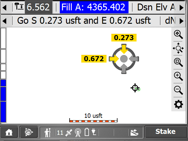
This accuracy is best used by surveyors and is a bit fussy for grading in general, so why would we use that detail? I always enforce the seperation of field layout and actual staking done by a surveyor. Our layout of a point is only a snapshot of the surface and surrounding influences of other 3D data. This myopic focus will tend to take away the big picture view that is necessary for site work. Sometimes you just need to nail a spot and point layout gets you there. Here are some instances where spot layout is beneficial.
- Confirm a building corner for sidewalk offset.
- Bases for hardscape items and playground equipment.
- For curb layout we will often provide 3-foot top back of curb offsets for layout as well as pc’s pt’s and radius points for curves.
- Street and road details. Staking station and offset is quick with points.
- Lightpoles and electrical stub-outs are easy as points. Electricians will not have the technology to make sure you won’t need to dig up the asphalt due to misplaced electrical.
- Fire hydrants, bends and tees. This gets into as-builts which we will cover later.
- We do a lot of 3D point layout for storm and sanitary on projects. Flow line excavation and locating is much easier with points.
- Parking lot striping has been laid out with points with good results.
The list can get longer as users become comfortable with equipment and perform basic tasks quickly. If you want to do more, we have a list of things to do with point layout that can keep users as busy as they want to be.
Points in Surface Preparation
It’s obvious that points are going to end up being used in building a surface. What I want to cover here is what happens when you use a point that was not obvious. We get so wrapped up in what we use for a surface, take all the engineering data and build. I have seen users try all sorts of fixes to lines and contours when a simple point would make it all better.
Corridors
Job Sites
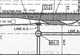
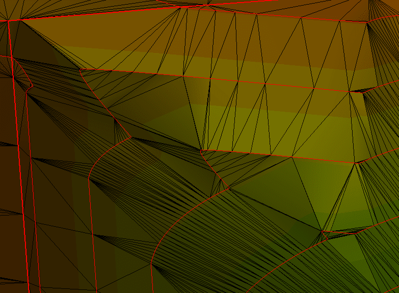
With little change to the surface for a small inlet, there is no need to complicate things. This is flat here so the additional triangles and breakover angles are not huge. If the approach to the inlet was over 2%, it could have become messy.
Another area that benefits from points is controlled site grading. That is (usually grass) areas that need to drain or have structures like a playground. I will use points to make water move where it needs to as well as placing supports for installed items. Something to note here is that points for foundations, or bases, are not usually part of a surface model. The grading around these areas are often below the concrete and would only distort the surface. These would be added to a list of layout points to be laid out when it came time to dig footings.
General Rules
Contour Grading
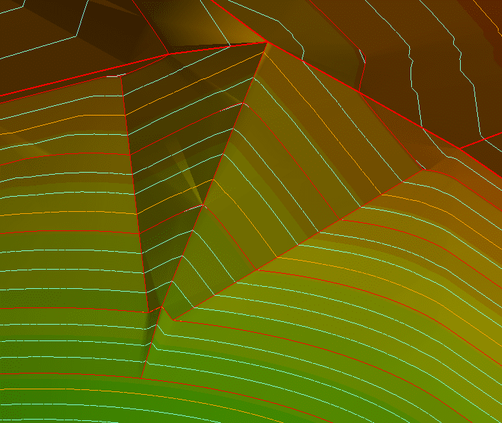
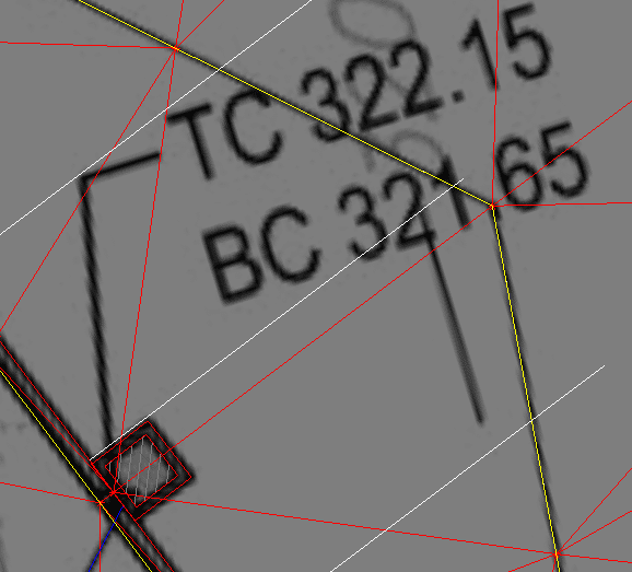
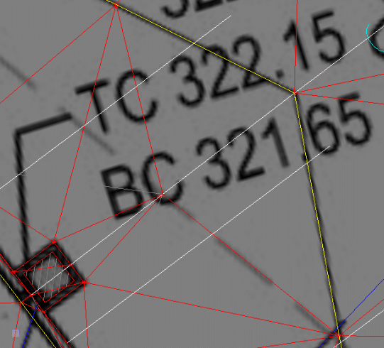
I ran break lines along the top and toe of the drainage swale. This cleaned things up and now water will flow better. Any time you add points by the addition of a break line, make sure it does what you want it to do. I’ve seen a lot of additions that are not needed for a good model. Surfaces are best when the minimum number of extras are added.
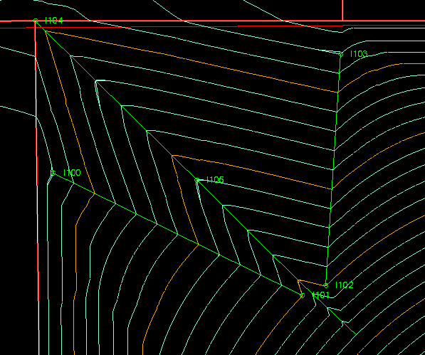
The basis of this article is what we call “named points.” A named point is a point you will most likely list and stake to at some point during construction. They also get included in surfaces as well as used for locating. Cleaning up of the ditch, as shown in the image, brings up an idea. This could be easily laid out as a surface. In this case, there is a concrete liner that gets placed in the swale, and points help to get things right. When the surface looks good, we will add layout points so the form carpenters can easily set the forms for the pour.
Point Collection
When a point is shot, you are doing it for a specific purpose. That eventual use dictates the collection method employed. GPS is an accurate tool but that changes with conditions and collection settings. A topo point will take a second. When you are shooting top of pipe for as-builts a longer occupation is better for improved accuracy. GPS increases vertical accuracy with a longer occupation of a point. The x, y coordinates will not shift much with increased time.
When you first initialize a site, the time you cook on control points can be as long as three minutes to get a good result. That time would be a waste if you did that for all your as-builts. Know when less can be as effective for the work at hand. I have seen field people not take enough time to get a point collected correctly. Don’t use topo collection for critical locations that are going to be covered up and accessed in the future. That information will eventually end up on a GIS database somewhere and others will use it for planning and excavation. We are making a long-term investment in getting a workable map of our work to make things easier in the future.
Point Organization
I can’t take the high road here. I start as-built collection with correct P Codes (Point Codes) and somewhere along the line I forget to change the code and my great field to finish idea is gone.
- Establish a company standard for point naming. This should be done for layout as well as collection.
- Try to set codes in the field as you collect. If you mess it up, don’t abandon the idea, just get it right again and fix in the office.
- Collect more points than you need and more points of random areas. They will help tell the story when in the office.
- Set up field to finish codes with company standard point naming. This is fluid and will change/improve over time.
Yes, points are part of a surface, but using them to locate and collection later is something you need to do and get good at. I will address field to finish solutions in the future. For the time being, get set up with a smooth transfer of point information to and from the field.