Maximizing Road Subgrade Efficiency with GPS Technology

Maximizing Road Subgrade Efficiency with GPS Technology

When spring rolls around, road construction gets into full swing. Road contractors have been early adopters of technology and continue to drive the development of new applications and equipment. Among them are laser augmentation for vertical accuracy and the automation of paving and curb machines. To improve efficiency, contractors should use technology wherever possible. This includes preparation of dirt grades and the application of subgrade materials.

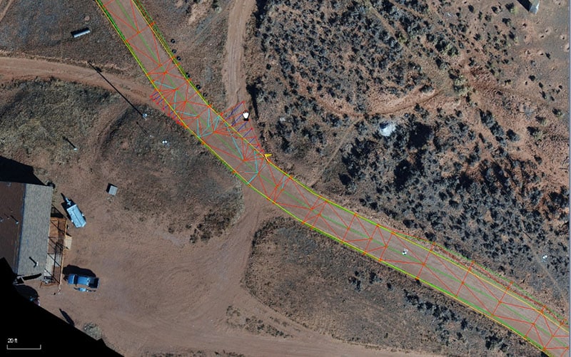
Optimizing Standard Road Subgrade Construction Techniques

When working with a site, it is easy to “dial down” the surface in order to grade to the top of dirt, compacted subgrade, and rock. This vertical offset works well, even though it just lowers the entire site to the set amount.

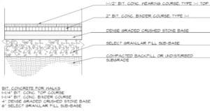
This drawing shows three (3) layers that can be installed using at vertical offset. With a well prepared subgrade, it is possible to pave using sonics and obtain good results in a basic parking lot.

For many road jobs, the subgrade is easily set with vertical offsets. A typical road design for urban rehabilitation work is one example. Here we see top of dirt and a prepared native subgrade that can be done with vertical offsets.

The subgrade extends beyond the road/curb finish. To make this easier to model, just the finished surface can be built. The equipment operator can run the blade down the road section and use sonic and cross slope, or a horizontal machine offset to pick up the additional two feet.

Techniques for Achieving Extended Road Subgrades

Another layer of difficulty is added where side slopes are built into a roadway. The subgrade hinge represents the intersection of the side slope and the projection of the subgrade. It is shown in this drawing inside the red circle. Refer to the video for a better understanding. There are two ways to accomplish the production of the subgrade hinge, office calculations or field adjustment.

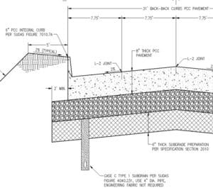
Office Calculated Subgrades Software programs can build the subgrade for roads with extended hinge points. It requires the data builder to build “another road”, adding time and complexity to the project. The result of this work is a new surface that represents the top of dirt grade where the subgrade and side slopes can be graded as one surface.

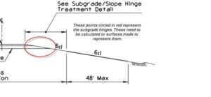
Often there is not enough time, or the data builder may not have learned the process. The field crews can establish the hinge point by the following method.

Build the road to finish grade. Establish the side slopes and begin grading them. At the same time, machines working the driving lanes can check the progress of the dirt grade. The machines on the driving lanes can dial down to the top of dirt, as long as they do not break over to the side slopes. Using horizontal offsets, the driving lane machines can work with those on the side slopes. The hinge point will result from their work. My YouTube video will clarify this.

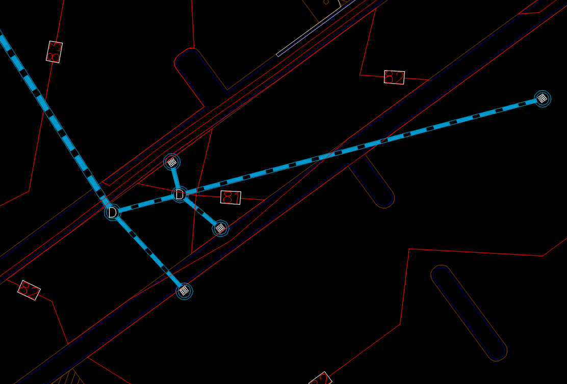
Navigating the Complexities of Multi-Layer Road Subgrades

Often, roads are done in two complete stages; from actual bidding to execution. The earthwork is part of one contract, and base and finish is on another and comes later. We see this in areas that have limited work due to weather constraints. In these areas, subgrades may not follow the cross slope of the main lines in super elevated sections. We have seen tangent section subgrades that are different cross slopes than the paving. Conditions like these require a full office build of the subgrade, as it changes cross slopes at a different rate than the paving.

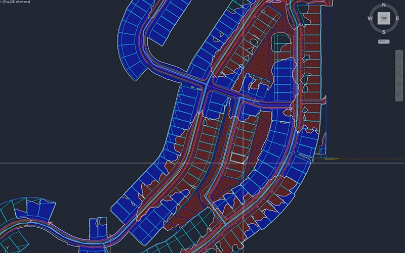
A complex road subgrade benefits from machine control. It also requires the production of at least one additional surface for the subgrade. The additional work is rewarded with a better product produced in a shorter amount of time.

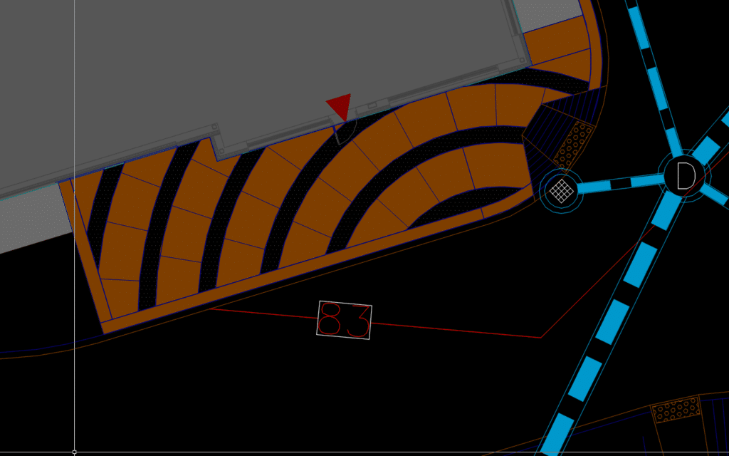
Precision in Locating Compacted Hinge Points for Road Subgrades

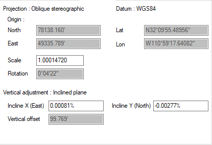
When building a road subgrade model, we know the finished location of the hinge point in 3-dimensions. If you don’t make all subgrades in the model the hinge point, the surface you are working on may not be called out. I will cover a work around in detail.

When this information gets into the field, the dirt either needs to be laid flat to compact to grade or compacted high to trim. With expensive subgrade materials and expensive geo-textile mats, there is no room for error. Here are some methods we employ to make this work.

Essential Practices for Trimming Road Subgrades to Perfection

When you get compaction on select fill in a subgrade planned for trimming, the trim amount is often not specified. We have seen times where you need to overbuild to 5-hundreths and trim, but this is the exception. Here is what we do:

  • Run tests with real world natural conditions, meaning the OG may compact more in some areas. Test compaction amounts of the select fill and adjust if the material spec changes. A close relationship with the supplier will help here. The biggest change we see is moisture. Some fills will respond to high moisture content poorly. Once everybody is happy with the testing, closely monitor the first few instances to confirm. Stringless trimming is the way to go here.
  • The road model is also what was used to produce the subgrade model. Trimming fill is cheaper than grinding concrete, so this is your first check of the roadway model. Any adjustments made in the field need to go back to the model builder so that the finished paving can reflect updates. We see this mostly around bridges, drainages, and tie ins.
  • A trimmer needs the same setup quality a paver does. I have seen trimming crews run a bit fast and loose with subgrades as the stakes are not as high. Watch closely.

Strategies for Managing Multiple Road Subgrade Layers

It is possible to model all the subgrades in a road job. We have all seen, and marveled, at a well compiled model that allows us to quickly create a model of a surface. Material types change during a project as well as thicknesses. We want to keep up with the changes, but it is easier to dial down from finish and intercept the side slope.

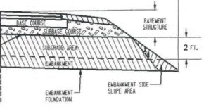
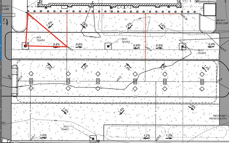
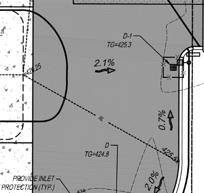
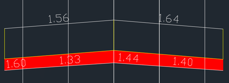
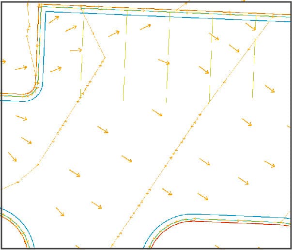
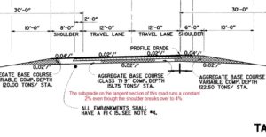
Here we see a paving section where multiple materials intersect and even stop short of the side slope. The called out “Embankment Side Slope Area” is drawn differently than it will be graded. Most will run the subgrade and embankment to the side slope.

In building this model, there are multiple hinge points. The best way to address this is to get the side slope close to right and run the subgrades out to the hinge. There are some precautions that you need to be aware of:

  • The BIGGEST issue that needs to be addressed are correct slopes and daylight lines. Be sure you have a tight ground model to model. Only then can you rough cut the side slopes to get the hinges right with less material use.
  • Compaction of embankment will be a moving target. Watch compaction of different soil types.
  • Don’t think you’re wasting your time building different subgrades. They make sense for a lot of jobs.
  • When automating paving, we will build a track grade model that sometimes changes the hinge point during construction. A final model is used to get the slopes back in line after.
Working with Surveyors

Working with Surveyors

Many years ago, I proposed that machine control would change the surveyor’s role and made it a point to discuss this with many state surveying groups. As a rule, surveyors need to be exact. A circumstance could come up where one would have to defend their work in court. With the need for accuracy, surveyors were not happy with contractors bringing precision equipment onto a site. Some thought contractors were cutting costs by reducing survey crew trips to construction sites. However, the real reason was that a surveyor may have to go back and tell a contractor some of their work was done incorrectly. Every surveyor hates to return and re-pound stakes that got knocked over, so how do they make sure the contractor can perform great work independently?

Survey Builds Data

I have been involved in lively discussions to legal debates over the production of machine control data. Regardless of the state, the answer is always the same: data built by or on behalf of a contractor is not an issue. Once that got settled the question remained, “Who should build the surface you will grade to?”

Traditional Surveying

Survey is solely about points. Load calc points into a data collector and go out and place them on the ground. The contractor connects the dots and a surface is made from the points.

The image at the right shows what we were given in a set of plans. Points found on the plans are placed on the ground in three-dimensions with a stake. The cut/fill to the desired location was marked and the dirt was moved. When things got close, blue tops were placed with the top of the wood stake at finish. Other types have a staple in the top holding the whiskers, a good operator would “polish” the staple and get grade that precise. The difficulty in this method of staking/grading is what happens between the hubs, a low spot or incorrect drainage is easy to miss. Only when a lot was paved would the problems show up. No matter how much spot checking we did, sometimes a spot would get missed.

Data Models

When I started doing this work, the only frame of reference I had was how things were staked and cut in the field. Because first generation equipment was difficult to use and problematic, training and ongoing support were normal. I spent more time in the field than in the office. We would build the model and I would be in the field for days, to weeks, training crews and getting a better idea of how to leverage the data that I collected.

The knowledge I gained by working in the field allowed me to create workflows that are now commonplace. The other problem we faced was that nobody knew how to build a model, but surveyors felt they were the best option. This is a learned ability and with practice anyone can become proficient, like me for instance. I worked long and hard to figure out how a model works in the office and the field. Coupled with a good understanding of how the mouse clicks transferred to the ground, I began to connect those dots. One of the most frequently asked questions I get is who the best candidate for a data builder is. I find it easier to train a computer savvy field person than try to get a CAD expert to think in three-dimensions.

In time, more people learned how to create good data and software ran ahead to improve commands and performance. The future holds the key to 3D design and implementation of data into the field. BIM has taken the lead due to multiple trades trying to occupy the same physical space. Currently much of that design work is done with CAD technicians producing the 3D models suitable for construction.

The ability to design, (or produce 3D data from CAD and plans) is mature. We will discuss the integration of surveying and data.

Cross Training

As more contractors started to create their own files, surveyors were not building as much data but keeping busy doing the important job of positioning. It’s necessary to understand what a surveyor does, but not actually do it. Surveyors need to understand data but not necessarily know how to build surfaces. Here is what each needs to know about the other.

Somebody must make a model for the machines to work. With model in hand, it’s time to go to the field. Surveyors are critical to any job large or small. I have seen the start of too many jobs by well-meaning contractors placed in the wrong spot or incorrect elevation. The nuances of positioning are complicated, and it is the surveyor who can assist in correct site placement. The GPS lead on the jobsite needs to have some of this ability too. The most important thing is sensing an issue and when to contact survey for work to be done. I have a surveyor friend who ten years ago would build the model and give the contractor a rover with the data loaded. They would start the job and call when they needed something.

I need to be clear; office and field civil construction workers are not doing survey. We are laying out and grading to information the surveyor knows is in the right place and will perform as intended. That is the end point of data and survey working together, so how do we get there?

Data Prep

I’ll run through the process when we work with a client on a typical site job.

  • We build the initial model and do the following:
    • Fix obvious errors and note them.
    • Make grading changes to reflect proper water flow.
    • Verify dates and changes to the plans to confirm current versions.
    • Report these changes to the contact(s). Usually this is the contractor. As the jobs get larger, we are often asked to communicate directly with the engineers and surveyors and include the contractor in the discussions.
  • Responses are received regarding questions.
  • Data is updated and work continues.

The data needs to start out as a representation of the finished product. There may be changes pending but not so detailed that we must redo a lot of dirt work. This rough grade file will keep the schedule moving and let the engineers know how long we have until we run out of things to do. Hard deadlines go both ways, stakeholders need to know we are faster at moving dirt and need answers to questions.

Your surveyor is invaluable at this stage, coordinate values need to be correct, the best way to know this is to bring them in early. As hired guns, we communicate with survey crews on jobs all the time. Be sure to do this early and with all jobs.

The next step in confirming data is to bring in control and verify locations and accuracy. Now that things are in the right spot and the data is close to correct, we can send the data to involved parties and gather input. Don’t expect a lot of information, everybody is busy, and most don’t have the time to review your data. It’s more of a courtesy.

Survey Functions

I have often been involved in some very detailed discussions about survey’s role on a job. I am an expert witness regarding disputes that sometimes involve surveying. I am no surveyor but have a good grasp on the practice. It takes time to be good at this and I leave it to the professionals.

The surveyor needs a plan for what they will do on your site. This prevents duplication of effort as well as ensuring it is going correctly. Here is a list of things to get right.

  • Understand what a site calibration (localization) is and what the report means. These numbers are critical and you need to understand them. When the surveyor is using different equipment than you are, you will need to perform this on your own. Compare the results to theirs to verify.
  • Know the difference in collection times. Sometimes you can walk and click, and other times you set up the bipod and cook for a minute. This affects accuracy and a few more seconds on various point types will be rewarded.
  • Respect procedure. Don’t take phone calls or talk to people on site when you are involved in critical tasks. When the surveyor tells you not to bother them now, it’s not because they are a jerk. They are in the zone and don’t want to miss something. When you are laying out curb points for example, always do things the same way. For example; I always do PC, RP, PT. Pick your method and stick with it. Here is a simple curb layout. This is what I want to see when I’m laying out.
  • Perform daily check-ins. Know that when you start your day you are as correct as you were yesterday. Do this for rovers and machines.
  • Share and listen. The information needs to go to the surveyors and engineers for review and comment. Again, you will not hear much, it’s just good to let them know what things look like in the field. This is a big advantage on remote jobs.

To wrap things up, learn enough about the other person’s job for better communication and efficiency. None of us can do a job that we are not trained for, but an understanding of the roles around you will go a long way in making things run smoother.

Regarding Civil Site Takeoffs

Regarding Civil Site Takeoffs

The request for “a quick takeoff” means different things to different clients. When a client makes this request, I generally know exactly what they need. The quick dirt number I provide usually leads them to knowing how much Teflon tape they’ll need for the water pipe joints.

The procedural filters we use while doing a scope of work will change over time, coinciding with the different stages, to make our job easier and more productive. Clients each have different requirements for their takeoff, eventual bidding, and final production. To walk you through this process, I will begin with the basics and investigate advanced ideas while I progress.

During this offering, I will speak in the first person, like it is “our job,” acting as a consultant who will perform the takeoff and processing services for our clients and not perform the work ourselves.

Just a Takeoff

When we “old timers” used to receive a request for a takeoff, the rules were simple and worked well for years. With more technology introduced, the deliverables clients expect to receive are much more advanced. Acquiring additional information, in respect to a civil site takeoff, may help you get your numbers right. The data in hand is purely for bidding purposes, but clients often want more information than they need. It only wastes their money.

Takeoff to Project Management

Once a client has won a job, I am all for details and more information. Many of you know my old line, “if you’re using your takeoff for data, you are doing too good a takeoff.” The same holds true for takeoff detail. If your takeoff can instantly become a project management document, you’re wasting your time with a too detailed takeoff.

The difficulty comes from transitioning a file from takeoff to production. Many think that you need to start over in order to make things work for production. As an old timer, I would agree with this, but industry software has made this a non-issue. Here are some of the transitions we need to make when the job is won.

The Dirt Number

As an experienced estimator and large-scale project manager, I always keep some money safely tucked away in different scopes for the eventual rainy day. The dirt number was one way to do this. During the bid phase we might have listed the strata from bore logs, but often they are not available, or time won’t allow it. Now that the job is ours, I start the deep dive into the actual cost of dirt moving and investigate the following items:

  • I get our drone, or hire a local drone operator, to fly a pre-start topo. We all know once you mobilize to a site and put a tooth in the ground, all bets are off for another trip to the well for more money because the OG information supplied in the plans was incorrect.
    When we get the topo information, the takeoff is rerun. If we are better than before, I use the advantage in my rainy-day fund. If the numbers go bad, we call a meeting with the owner and renegotiate. Make sure this is all done before digging. When fast-tracking, you still have the date the topo was flown as well as images that show no disturbance. An email to let everyone know this is an issue will serve to keep the issue open until a change order is processed.
  • The different amounts of each type of dirt that needs to be moved is the next area I look at. If you had the bore logs and they were entered into the takeoff numbers, review them and start to look at actual costs for handling each material type. Many contractors know their areas well and will assign an average dirt number to the quantities at bid time and come back later for refining. You can now figure amounts much more closely with additional information.
  • For mass haul analysis, cut/fill and enter our average number for dirt moving works well for bidding. These quick numbers are a result of careful figuring based on prior work and should get you in the ballpark to win some of the hard-bid jobs you go after.
  • When you get the job, it’s time to start drilling down into the numbers and squeeze those few percentage points to make the boss some money. The amount of dirt getting moved at what distance on what quality surface is the breakdown. I will review a site mass haul in the video and go over what I look for in the reporting.
  • Many site jobs require going offsite to dispose or import material. This is another chance to make some calls, shorten distances and lower costs. During the bid, you might have used local numbers or made a quick call to plug in a price. Now is the time to get some savings from the averages used in the proposal.
  • Now that we have won the job and returned from the celebration, it’s time to be good to the owners, and help us a bit along the way. We all need to bid to the plans and specifications and consider the pricing on additions and alternates. There are too many variables to go over here, but each contractor knows that there are a lot of better ways to do certain parts of a job than what’s been drawn by the engineers. We see the biggest disparities in chain business when plans have been drawn out of state without intimate knowledge of the area. Others have some luck by having worked in the immediate area and are then able to recommend some changes that will enhance the job and save everyone some money.

To this point, I have used quick and basic takeoffs that drove the dirt numbers without having to redo anything. I just spent more time drilling down in the listed areas. I made a lot of owner’s good money by being diligent in the above areas except when back in my day we walked the topo, drones weren’t invented then.

You need to perform the above first. This ensures the original ground information is good, you understand conditions, as well as knowing how far you’ll need to go for material import or export. With this completed, it’s on to the next phase.

Project Management Process

A lot of time is wasted moving materials on a jobsite. It could be dirt that was set incorrectly. To pipe and other import items that always seem to be in the way. We now need to elevate the quality of our data from a takeoff to a performing site data model. The big question is whether to start over or improve the takeoff to data quality. Here is my process:

The Big Stuff

My first question is, did the overall footprint change? With the basic layout still intact, the improvement of the takeoff is my first choice for a data model. We already have the layers broken out and most of the COGO (Coordinate Geometry) is good.

Many times, there are changes to the plans after we have won the bid. Hopefully some of them are from our value engineering proposals to the owners and engineers. With that information in hand, a fresh look at the model will tell you if you should start over or improve things that were in the takeoff. With good layer naming and consolidation, it is not hard to add islands or redo a changed curb line. Resized retentions and other common areas are easy to remove and replace. I will go over a few of these points in a video regarding the use of layers and how to use them to your benefit.

The Details

When we do a takeoff, little attention is paid to making a parking lot look great. We elevate curb lines and possibly change bad spikes. I have done countless studies and presentations from a takeoff to data model quantities and the difference is miniscule. The price of a data model is about 3-times what a takeoff costs. It is not worth our client’s money to get crazy detailed with a takeoff. During the bidding phase, plans are often not approved by all agencies and will change before being issued with final approval. It is important to note the delta changes on the latest and greatest set. A word of advice; never trust clouds on the plans to indicate all the changes made to the job. I like Bluebeam sheet compare for this, I will do a video to explain.

With a final set of approved for construction plans in hand, we can get to work. Let’s elevate the takeoff data and prepare it for construction.

  • Drill down into the dirt as explained above. Get those numbers correct and detailed.
  • Break out the job the way you need for phasing and ordering. You have gross numbers, now you can meet with project managers and superintendents to organize things better.
  • Verify the data model is good, (at least for now) with current changes. During data building, we will find issues and submit questions. In the mean time, you can leave the data as-is for the rough grade phase. If the questions would affect the initial mass earthwork calculations, leave the area blank in the model until you get guidance. Don’t move dirt twice to look busy.
  • Add numbers to the quantities. All current takeoff software can export to your spreadsheet estimating program or Excel for adding prices.
  • Go back to the takeoff and add any additional information you want to run through the process of measure, export, and price. We will do everything from count light poles, measure striping, breakout straight and curved curb, and place playground equipment bases. With the plans in front of you digitally, we find it good to even measure items that will be subbed out. It sure is nice to adjust a supplier’s estimate and save some money.
Paving Rehab Data

Paving Rehab Data

The U.S. Interstate Highway system is almost complete. Regional networks are mature, and the new right of way is geared for housing. Luckily, we still see new alignments and the percentage is increasing for repaving and full reconstruction. This increase has led us to become efficient with sometimes difficult road improvement jobs. Let me explain.

Types of Rehab

There are three basic types of road rehabilitation all requiring a different approach to the data. While I have defined the types for data purposes, there are projects that can be a combination requiring a change in the process.

Full Rehab

This is the easiest and currently the most popular type we perform. The road may move horizontally and/or vertically and none of the previous roadway elements are to remain. Paving, curbs, and driveways are all replaced. Ditches will usually be reworked, if there is an underground storm system, it may change as well.

With everything being new, it may not make sense to refer to this as rehab. The reason is at some point the work you are doing will need to connect to something that will not be moving. Driveways, buildings and off-right-of-way drainage are required to match-in with the least amount of disturbance possible.

Mill and Fill

Asphalt paving does not have a great life in many parts of the country. Freeze-thaw in the North, water and heat in the South, and brutal sun in the West define the finite life and eventual repair of the wear surface. When spot repair is no longer possible, the road surface will be milled, and a new full-depth mat will be laid on the freshly compacted base.

We will go into detail later, but the curbs are usually in good enough shape to keep. We are now required to respect the vertical and horizontal constraints of the existing road. In addition, there are required minimum and maximum coverage and lifts for the base and wear surface. This gets difficult to work with, as there are many constraints plus having little or no ability to try and fit everything in.

Widening

Right of way acquisition is usually done with the future in mind, especially with larger arterial roads. As traffic counts increase, lanes are added to accept the load. When confronted with a widening job, we are concerned with two major points. First, the condition of the edge we are joining to, and then the topography of the extension. I will detail these in a moment.

The Basics

When doing rehab work, we usually go the route of a road job. Alignments and templates are a good start to get things right and, most importantly, a way to easily adjust as things change. The single biggest issue with rehab projects is the dynamic nature of all the parts that need to come together. Here is an outline of what we like to see.

Horizontal Alignments

Ordinary COGO (Coordinate Geometry) will be provided when doing a new road. Sometimes in a rehab job, the plans call out for following the existing road center. Yes, this is a loaded statement from the designers. There may be a line on the plans that might be an old alignment, or something drawn for convenience. Alignments with good instructions are easy to get on your screen, but what about that mystery scratch in the near middle of the road? There are several alternatives.

If you can’t get a good centerline from the CAD, you need to decide on how to guide machines for the work. A best fit centerline takes the edges of pavement and averages the distance between them to give you something to steer to. Here is a set of shots that were taken along the existing edge of pavement along the slip formed curb/gutter.

There are many ways to get an alignment, in this case I am using Carlson’s Best-Fit Centerline. You can use points or lines. Here I drew lines through the points with arcs in order to give the program a smoother start to figuring out a centerline. The alignment is drawn through the upper line (shown above) and will offset to get it to the approximate center.

I often times will do this on the other side of the road as well. When this is necessary, you need to either make a new averaged centerline or create two different roads using one for each side. These cases are generally for older, small streets and roads where environmental conditions have caused heaving and erosion to move the curb. Logic says we will replace those sections so this is a rare exception, not the rule. Knowing that, you are now able to fix real issues.

The new centerline is shown here. It deviates from the edge by almost 3-feet in the worst spot. This is too much. Changing the parameters will tighten things up. This is shown in the video.

With a good alignment to steer to, we will now work on the vertical.

Vertical Alignments

With horizontal alignments we are trying to get a centerline close to actual. With a vertical alignment, the stakes are higher. When the vertical profile corresponds with the centerline, it must follow road speed rules regarding cross-slope and the finished job needs to look good.

The job depicted above has 3D shots along the edge of pavement, as well as, centerline shots that are turned off. With these 3-points acting as cross-sections, we can create a good existing road surface as cross-sections. Don’t be alarmed if a contoured surface looks bad, a cross-section look is the best way to generate a finished product.

I have used Carlson’s Road Rehabilitation Profile command with good results. You will need to get things in order, including some of the outlined steps I will reference. When the pieces are in place, you will have access to the options shown in the dialog box. Lots of power is provided to automate a sometimes-difficult task.

With the alignments done be assured you will be revisiting these to make things work better. We will generate cross-sections to verify the quality of the data.

The following is the Carlson section alignment dialog box. There are enough options to give you the results you are looking for. I am using these options for the job in this article.

With the section interval and special stations defined, I will now create sections of the existing road to give me an idea of what I’m looking at.

Gathering Existing Data

I need to mention a critical point. When we work with clients who build models, we insist the shots are taken with a total station. GPS accuracy is not reliable for the number of required shots and would take too long to get low residuals. A robot and one person can shoot quickly and with accuracy to make sure we are not wasting time. We accept GPS shots only to fully rebuild the job after receiving good data.

Section Review

The production of cross-sections will be the true test of what needs to be done next. I have spent a lot of hours getting things ready for production on rehab jobs. The constraints of the existing features that remain and the rules imposed by the parameters of the road design make the task difficult. It may be necessary to rebuild the job several times in order to make everything work.

Also be aware of the hierarchy of importance in case something must give. For example, we need to keep the curb but need to go less than the required 2% slope. That’s an easy one, but there may be situations where several rules need to be flexed for things to work.

Here is one such example. The road is straight and calls for a 1.5% cross-slope. The right side of the road is almost flat. We need to review up and down station to see how far this extends. The solution here was a 75-foot curb replacement due to heaving of the existing curb and gutter.

With requirements that are often out of the requested values, this type of work takes more time. Many rehab jobs just want to follow the existing road, mill the existing surface and come back with minimum cover. This type of job still needs data to work correctly.

Carlson has a tool I have used with great success. The Match Reference Section Slope command allows you to specify the desired slopes and the limits of deviation to it. Here we are trying to get a 2% cross-slope with a variance to try and make things fit better.

After filling out the dialog box, the command has listed the varying cross-slopes generated by the settings.

Adjusting the Parameters

There are two tools I use to verify a rehab design. The first is the actual material to be used. At some point there was a takeoff done, and I want to make sure we are in the ballpark.

This is just a portion of the report, but the totals are in line. To adjust things, go back to the Process Options dialogue box and check the Adjust Template Grade Table. The side not associated with the Profile Grade will adjust. This may push the slopes outside the design parameters and require a variance to get the volumes down.

I will then plot the sections to verify the profile is doing what I want it to. With a small road like this there is not a lot of room to move, but if the job is several miles long small tweaks can bring big savings.  This particular road is getting 8-inches of white paving. The red is the sub-base needed to bring this up to grade. Had this trend continued for several stations in both directions, I would revisit the vertical profile to try and pick up some material savings.

Summary

The task may sound daunting, but the job needs to be broken down into the individual parts that make up the job. I have tried what seemed to be quicker and easier methods, but changes are near impossible and always take longer.

Approach each part of the process as a separate task and the delineation makes things easier to imagine. With more of these jobs coming along every day, it pays to be proficient.

I have featured Carlson because I have experience using the commands for road rehab projects. Other software can accomplish the same tasks. The commands will be different, but the procedure remains the same.

Curb Alignments for Machine Guidance

Curb Alignments for Machine Guidance

More contractors are taking advantage of stringless curb technology today. At TOPS, we got involved with stringless curb when it was proposed as an alternate application for machine control. In their quest for increased productivity, some of our clients are early adopters which we credit with our first-hand experience in using the technology.

The Concept

The idea is straightforward. Adapt the use of alignments for paving systems to a curb machine and eliminate the string. There isn’t more to do for the transfer of the guidance and the technique seems easy to perform. Unfortunately, we encountered some problems along the way. But lucky for you, we have taken the time to point them out and guide you on this process.

Stumbling Blocks

You need to build an alignment-based project that has the usual elements, horizontal and vertical alignments, and a template. Brands vary but the template can be used to pick the side of the alignment the curb is on, as well as, slope for fill or spill curb.

One of the difficult things to do is to make the alignments as if you’re in the field doing the work. This varies for our clients and it is something you need to coordinate with the curb crew.

In the example here, I bring up two interesting points:

  1. This job is the addition of more parking to an existing lot. When joining to that curb, we need to get accurate shots in order to smoothly pick up the slope of the current to future curb.
  2. The 90-degree corner will necessitate a stop in the alignment. The question for the field is where to start one alignment and stop another.

Alignments

As with any road job, a horizontal and vertical alignment are required. With curb, things need to be different. There will be some figuring with both.

Horizontal

Each curb is a separate road job. As shown earlier, you need to coordinate with the field as to the start and stop points. Experience has led us to have this consistent, but it takes time to coordinate. When you get it figured out, it will stay standard for the most part.

When working with a closed island with all curves, the line needs to either stop short of the end or go past it and not be on the same path. This example shows the alignment stopping .10 feet from the start. This gives the machine a chance to complete the run without the software problems of an alignment running back on itself.

We will also have the alignment bypass the start by a couple hundredths of a foot when it gets back to the start point to keep the lines from intersecting.

While building the alignments you are also providing a full takeoff of the curb so the field can schedule concrete and plan the pour accurately.

Vertical

This is where things get interesting. We all know that good plans have elevation callouts for the major points of a curb. This example is trying to do that, but this job has sheet graded contours that make things more difficult. We need to pay attention to closed areas that may trap water and make them back-flow into the main slope plane.

Breakover Angles

This is by far the most critical part of designing stringless curb files.

Here are the elevation points as called out in the plans. The curb moves along but there are angle breaks with a 2% delta. When entered into the machine like this they will cause it to abruptly change slope and make a mess. To remedy this, two things must happen.

  1. Vertical curves must be added to the alignment to smooth out the transition in slopes. Our method for figuring the amount of curvature has been derived through experience working with machine control and curb machine vendors. Experience will need to be your teacher here.
  2. After making the curb look right, the new edge of pavement 3D information needs to be incorporated into the model so the subgrade and paving are not affected.

Here is the alignment after the addition of the vertical curves. The transition is now smooth, and the machine will make the slope change gradually so things look right and perform well.

In the images, the difference may seem subtle. In the field, it is scary to see the machine try to do an instant 3- or 4-degree slope change. I’m sure the question will come up in a cart and horse fashion. If you are changing the parking lot surface, should you design the curb first? Most jobs don’t use stringless curb. The ones that do are usually requested after the surface file has been made and the curb contractor wants to use the technology.

The initial file creation is procedural and a process should be followed. This is because there may be 50 alignments for a big site job, and you don’t want to go back and check every line to see if you missed something. There isn’t much rework involved after the curb alignments are returned to the surface, we just want to make sure base depths conform to plan. The following is an outline of the entire process.

Create Curb Template Alignments

  • Save the file as a new version to keep the surface file alone
  • Create breaks for machine control
  • Create a vertical and horizontal alignment from the curb lines
  • Station the horizontal
  • Add vertical curves to smooth out the profiles
  • Create the proper exportable road file. Brands and requirements vary

Create New Surface

  • Do another save with a new name
  • Remove the use of the initial curb elevations in the model
  • Set the vertical profiles as the new curb lines
  • Offset the lines in three-dimensions to get the lines locations and elevations to gutter or edge of pavement
  • Adjust the surface in areas that make it smooth and well drained

A bit easier said than done, but experience has really helped us get this operation efficient. The curb files we make for clients can guide stringless curb with confidence. I remember years ago when the head of Gomaco asked me why I thought anyone would use stringless and how I planned on giving the crews confidence to spend tons of money and time with no string to lead the way. Here is what I stated and how a company gains trust.

  • The curb (or white paving) is derived from the model used to blade the surface. If that looks good, things are okay.
  • Use a 4-wheeler to do a dry run. Load the road job and drive along the curb, you will see any problems before the pour.

With all these advantages to stringless mentioned, file preparation is not a big chore. I have some sad stories about stringline that caused us problems over the years. A few dry runs of practice and maybe some “air-paving” will get you comfortable and ready to make the move to automating curbing and paving.


Using XML in Civil Construction

Using XML in Civil Construction

Extensible Markup Language (XML) is used throughout various coding and language platforms. In our field it’s used to produce and transfer data types for data prep and site construction. There are two versions of XML (1.0 and 1.1), and both will import into the current software used by civil professionals.

LandXML

The basic format for XML was a good starting point for different industries. Autodesk started the widespread use of XML and import/export ability was added to more software as the code matured. Most development by commercial software vendors began to drop off after version 1.0 released in 2002. Version 1.1 is capable of additional and enhanced data but never got the desired traction.

Enter Carlson

Carlson Software of Maysville, Kentucky picked up the LandXML development process and produced version 2.0. The addition of textures and advanced data types was a good idea, but support from other platforms is lagging. I don’t think much more will happen as 2.0 was in draft as of 2014.

This image is an import of a LandXML file imported into Carlson’s Precision 3D. It includes textures, polylines and field-to-finish data such as the light poles seen along the road.

If this file were imported into another CAD program not supporting 2.0, the data would be limited to surface elements. In other words, a TIN surface with faces and breaklines would be generated without any additional data.

Understanding XML

XML documents, in a basic discussion, are made up of markup and content. We also need to look at the header section of an XML document, as it contains information we may need.

The XML Header

Importing a file into your software is usually not a big issue. Bringing in CAD and point files is routine. An XML import should be no different. Where there could be an issue is with the XML units and how they are interpreted by the software. Let’s look at an XML header.

  • We know the time and date the file was last saved
  • This is a version 2.0 file. Software that only reads 1.2 will still import information, just not all.
  • Know which units were used in the file. Know your software, some will not alert you of a unit mismatch. An example is provided in the corresponding video.
  • We have our first look at a tag with the unit(s) callout.

Markup and Content

Markup begins with < and ends with >. Between those constraints lies the content. It also encloses tags which can have content following. Anything that is not markup is content. That rule is not absolute but for civil XML files this will be what we see for the most part.

If we drill down in this section we see a surface named All Roads and Drives.  A Boundary will be created using the PntList3D points. Note the points are not comma delimited. They are Northing, Easting, and Elevation in a continous string seperated by a space.

In the next example, the screen shot calls out several boundaries and the connected points to make them. The boundaries are individual markup callouts because each 3D line encloses a different street. This will start and stop line generation for each street.

Here is a 3D view of drawn smaller boundaries. This also allows the closed line to be used in texture rendering and vertical adjustments.

In this file the surfaces that make up the roads are shown after the boundaries are written. The markup and content give you the type and ID of the TIN edge verticies as points. When the points are brought into the file, the TIN edges need to be called out so they form correctly. Shown are the end of the TIN points and the beginning of the point numbers that form the faces of the TIN.

The production of the TIN faces, (edges) continues to the end of the file.

Here are some things you will want to find out before importing an XML file. Be sure to make a copy of your file so edits can be undone if need be.

  • Most critical to review are the units. U.S. and International feet can cause problems. Note that International feet will be called “foot.”
  • Determine the software that produced the XML. This can come in handy. It doesn’t happen often, but files produced by different platforms don’t always import properly.
  • The XML file may contain coordinate system information letting you know how the job was set up.

  • Sometimes you may not want all the information provided in the file. You can clip out the tags and related elements you don’t want to import. I agree that all you need to do is delete the unwanted element. However, that unwanted element could be a huge surface or something that stops the file import and shuts down before the elements you want get put on the screen.
  • The original project name is often times included as a tag. This can help you verify dates and times to confirm you are working with the latest and greatest.

Why Use XML

The ease of producing, sharing, and importing XML files has made them the format of choice for data transfer. Large scan and photogrammetry surfaces can be easily digested by smaller office computers as opposed to point cloud formats.

With this ease, many people are transferring data in this format. I have outlined some steps for users to make file sharing easier. The knowledge gained by reviewing the raw XML in a viewer cannot be over emphasized. Take some time to look at files that have worked for you in addition to those that gave you issues.

When you get to know what’s in a file by reviewing it, your confidence will increase as well as the ability to verify sources and validity of files. Work with some files and contact me with any questions or issues you have.

Update – September 2020

Recent questions have come up regarding problems with transferring data files. Here are some tips to those issues.

Outgoing

  • Be careful what you choose to export. I have seen exports become clogged and fail because there are too many different types of data in a file.
  • Old software may be limited to version 1.0 and not read 1.1
  • If you have issues with a file working for you and not the recipient, try zipping the file. For some reason, mail handlers and virus programs have tainted files. This is rare but if you get frustrated, try it.

Incoming

  • Never drag and drop an XML file on a program screen. Use the import function. There may be settings you are missing in bypassing the command.
  • No need to learn programming. But if you have a file that will not import, open it in a text viewer to see if the header looks corrupted. Compare to the examples given in this article.
  • Know what type of surface you are receiving. Most surfaces are comprised of TIN lines and breaklines. If your software does not separate them on import, you can make two copies of the file and strip alternate types to import to different layers.
All About TIN Surfaces

All About TIN Surfaces

The building block of a surface used in civil and architectural 3D modeling is the TIN (Triangulated Irregular Network). We will go over its definition, rules, and tips for making this format perform. Let’s get started.

The TIN surface

Definition

A TIN (triangulated irregular network) is the format used to transmit spatial ideas into something that can be transferred to the ground for civil (and architectural) work. A TIN consists of triangle definitions that have x, y and z coordinated for each of the three points. The triangles do not overlap and share common intersection points.

The triangles can be any configuration and size. The only limitation are the three sides. The triangles are all flat planes (NOTE: this will be important to remember later). When generating a TIN, you will often see some large triangles, some with long edges and some with very small edges.

The vertices of the triangles are generated from 3D elements provided from the following three elements you will create. They are 2D lines (contours), 3D lines and points. The vertices are made up of how far apart they are interpolated and elevations assigned to these elements.


TIN Faces

The connected 3D points that make up the TIN are TIN edges. They should not be looked at as lines but instead as a visual representation of the edge of the flat triangle. This will tell you where the grade breaks to the next triangle are so the surface will perform the way you want.

TIN Breakover

The TIN Breakover refers to the angle from one flat triangle to the adjacent one. This is important to mention because if the angle is too great, you can add more points therefore generating more triangles and softening the severity of the angle.

In this example, the slope between these two triangles goes from .48% to 3.47%. Smaller triangles have been added to smooth their transitions.

You may not always want smooth transitions. Starting with the top or toe of a slope, you will want to hold a 3:1 ratio as it flows to a flat bottom. In this case, be sure to add enough data points so there are no errant elevations in that area. This will be covered more later.


TIN Density

If 10 is good, 100 is better, or so we used to believe about surface triangles. The short answer to TIN density is to add just enough to make the surface do what you need it to. Currently, the advantage is that faster computers and segmented TIN handling have made things better. Field firmware can break up surfaces to load just the area you are working on and not the entire file.

Over the years I have come up with guidelines to help users get closer to the balance of surface, size, and performance:

  • Try and make all the triangles (in an area) the same size. This insures smooth edge transitions and helps large grader blades operate better. In this screenshot there are similar sized triangles in a parking area. You will need to add more triangles as things warp and not just slope like this example. Be sure to add where needed.


  • For this example, triangles need to be added because of the arcs on the parking islands and the changing slopes. These elements require that water is pushed away from the parking curb into the drive area. Never assume that the number or appearance of triangles indicates the quality of a surface. It’s just a starting point. We are looking for a surface that does what is needed for that job, which changes all the time.
  • Do not confuse TIN density with the actual point elevations you assign. Add points where the grade must change. Look at a surface like you are laying out points to grade to. A blade will connect those dots. That is where TIN density comes in.

Density Settings

Software can densify surface points when it makes the TIN. There is no need to add these points during the line/point process as they are densified in the settings when it is time to make the TIN. When working on a surface, we will not add additional points, so we can see the work we are doing. When we like the points/lines we have made, then we will increase point density. This increase in points will address the issues I have been discussing like breakovers and detail areas.

Business Center addresses this in the settings as the maximum sampling distance. I will also address the tolerance items in a bit.

Carlson allows the distance to be turned on and off while keeping the setting.

The horizontal and vertical tolerance settings refer to the middle ordinate of the cord that represents the arc. That distance is the maximum a chord line can be from an arc.

The red line is the TIN line and the green is the 2D arc. That setting will adjust the space shown here.

A good start for setting the distance number is 10 feet for small sites up to 10 acres. We move to 20 feet when things get larger than that to keep a good surface size. There are instances where you will need to adjust this but this is a great place to start.

Surface Review and Detailing

When you have a surface that looks good to you there needs to be a way to check it. You need to look at the appearance as well as the performance. Let’s first look at appearance.

Surface Appearance

To get paid at the end of a project, an owner must be satisfied with how the job looks. We have all seen poorly performed jobs that look great. Commonly the issue is that the performance faults appear after a crew has left an otherwise good-looking job. Depressions and bird baths in parking lots. Incorrect paving base depths and respreads thicknesses all take time to manifest and tarnish the overall appearance of a job.

The easiest way to see how a surface looks is to contour at a tenth of a foot interval. Subtle grade changes become obvious and draw your attention to the areas that need attention. This image shows good transitions and will not surprise a fast driver at the entrance.

To verify how the water is going to flow, turn on the slope arrows for confirmation of how water will flow when it rains and snows.

Take a close look at the parking stall in the northwest corner. There is a grade break at the south end of the parking stripe moving water to the northeast and then joining the sheet drainage to the southeast. This looks a bit odd but keeps the water moving out of that corner.

You also need to look at drainage areas. These areas need to keep water moving in the right direction and can also be used as common areas and playground facilities. The potential use of drainage areas varies without a lot of ADA requirements for slopes due to being primarily drainage. Be sure to review contours and slope arrows for correct directions.

Surface Performance

Now that the surface looks good, it’s time to verify the performance. At this point contours are not necessary, but I like to keep slope arrows on while moving around the project. I will go over this in the accompanying video. When reviewing a job at this stage, these are the things I look for.

Building

We usually don’t do much in data for the areas outside a building. When concrete is installed and grading is performed around a building, the GPS survey signals are blocked and the work is done with smaller non-controlled machines. In any case, make sure there is drainage outside the building envelope per plan. We often see 5% slopes for dirt outside the building.

Hardscapes

Any sidewalks outside the building as well as common area sidewalks need to be at no more than a 2% cross slope. We have some clients that have us slope to 1.5% for a margin of error to not exceed the maximum. Trail looking sidewalks are common in drainage and park areas, and sometimes have vertical alignments associated with them. These types of mini-road jobs need to be looked at where the alignments and sidewalk are treated like a roadway. In my experience, this is the best way to work through them. It may take a bit more time but it’s worth it.

Paving

After reviewing the contours and slope arrows we can confirm the surface will drain. This is the time to make sure the paving is done correctly. A big debate in our industry is the production of subgrades. I don’t mind having software build subgrades for a takeoff, but I don’t like to use them for production. The crossing lines and vertical jumps in the surface can affect a blade as well as not being sure that they are in the right place. A few inches thick paving on a takeoff is okay but will result in phone calls if it makes its way to the model.

We recommend dialing down in the machine or rover to get to subgrade. The fact is you must have the presence of mind to either load the correct surface or dial down. Either decision takes thinking it through and attention to the details. We don’t feel we need to spend our client’s money for building subgrade surfaces when field dial downs are better. Here is why. I can dial down to get to top of dirt in a parking lot, then pick the back of curb line and do a 3-foot offset to get to back of curb with room for the curb machine. Focus the 3D on the other blade tip and the parking lot slope will be projected to the back of curb. That surface cannot be made easily in the office and is quick in the field to accomplish.

There is a process we go through when producing site data and is tweaked by each of our engineers to suit them. Come up with your own process and stay with it. Productivity increases when you know what you have done and what comes next.

UPDATE – AUGUST 2020

I have received many questions regarding TIN surfaces after this article was published. There is a lot of confusion regarding how a surface looks on the screen and how it performs in the field. Here are some tips.

Consider the Use

The biggest question is, “What will be making the grade in this area of the project?” When you are near buildings in tight areas or a small retention, a grade setter will be there to call out or establish grades to be done conventionally. In a larger area where a blade will fit, machine control will be utilized.

When working in a constrained area, think about what you need to do for water to drain and sidewalks to meet code.

In this image we are looking at a sidewalk next to a building. This will be graded and leveled by a skid steer and laid out by hand. Here is what will happen for data prep in this area:

  • The sidewalk will be modeled at finished grade. In this case, we will go with a 1.5% slope in case it does not grade. We will remain under the 2% ADA max.
  • There could be trouble if the curb is not correct because there needs to be a straight grade from the curb to the building entrance. Pay special attention to curb layout here.
  • The ADA ramp needs to be set in the collector so the field has this information for layout.
  • Get some 2D layout for the alternating sidewalk/paver layout.
  • The best thing to do for sidewalk layout is to calculate the center point of the radius and let the field run line to get the curve correct.


In this part of the job, things are getting more open and easily done with a grader. Here is the approach:

  • The entry road is where you see a low point at 81 feet and storm structures. Add a vertical curve to make sure this grades well.
  • The peninsulas in the parking lot may be modeled depending on client preference. If we put them in, they will be manual across the curb bump but some like to see them in the model.
  • The isolated islands in the parking lot get ignored, so the blade makes a good surface for paving.
  • Think in terms of the blade, 10 to 14 feet of material will be graded and too many breakovers make the system jumpy.
X