The Bell Helmet Company once had a magazine ad with the statement, “If you have a 5-dollar head, get a 5-dollar helmet.” Wise words when you think about protecting your brain. The interwebs have done a great service to us; we now have experts in every corner of the world. I admire some of them but do an eye roll with many. As one of the original innovators in the industry, I’m not pulling rank, I am speaking from experience. I just do not like to hear bad information being passed off as truth.
Regarding those who advertise low-cost data, I have but one thought: If your work was worth more, you would charge more. So many people are not invested in making a good product, but just making a product. I have spent my career working on delivering data in the fewest mouse clicks possible. We like to bill for work done efficiently by trained professionals who have been trained by experienced mentors familiar with a lot of different data issues. When the experience issue gets brushed aside as a “nothing burger” by more recent entrants to the data industry, one has to look at the actual time it takes to decode and properly set up a project.
Many times when inexpensive data gets built, it is just converting a surface built by the engineer at some point in the design. This is usually done to get a rough dirt number so that some quantities can be put on the plans. When doing a takeoff and I was close to the engineer’s numbers, I went through things again. Those quantities are usually never close. The surface is not only a few changes behind the plans, it lacks the detail for successful grading. Here is why proper data takes a bit of time.
Initial Data Files
We receive the plans and CAD in addition to a work order for the job. We often find that the plans and CAD are a mismatch. Not a big deal. Just find out which of the two is correct, get the current file and we are good to go. For every job we do, the files get touched by no fewer than three software platforms. It is not cheap to have all that horsepower, but we can do a more efficient, competitively priced job with them. We need to read the plans and relevant specifications to insulate our client from issues. We want no surprises. Notes on the job guide our work, then we start building.
The Big Picture
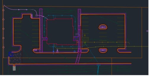
I will use a sample project to give you an idea of what good data, coupled with 25 years of experience, looks like. The data engineer working on the job has a deep bench of talent to call on for advice. A great advantage that goes a long way in securing a good job for our clients. Here are the basics:;
The entire job consists of a building with a basement, parking for 200 vehicles, and a long entrance road.
There is detailed landscaping along with a lot of drainage work, (wet part of the country).
We also need to build an initial water management surface, as all the water needs to stay on the project. Watershed pollution prevention.
Initial CAD Work
We have detail sheets that we populate for our clients. Surface density, line colors, file types, and delivery method are a few of the things that make a job easier for our clients’ field crews. As a former field hand, I like to be in their corner and do everything possible for them. Five minutes of work in our office on the computer saves 30 minutes balled up in the cab of a work truck, trying to change something. Here is the process.
Civil 3D files can be feature rich. That is good news for somebody doing poor work and just converting a surface. In our world, that is something we delete to make the file smaller.
Lines have become critical. A grade checker will want a 3- foot back of curb 3D line to set string or hanging forms. A blade hand wants to snap on an edge of pavement line to shift the blade 2 feet behind the curb for slip former access. All of these lines need to be in the correct direction, void of any overlaps and breaks. That takes time.
With the paper plans ruling, we need to confirm that the job looks like the CAD; this can be time- consuming and frustrating. The best that one can hope for is a spot check with budget data work.
In the early days, we worried about file sizes, but not so much anymore. It still makes sense to show only the lines necessary to complete the work. Text needs to be simple and in a format that does not steal bandwidth from a controller.
Surface Components
Since the beginning of the data business, we have used the same elements for building data. Each of these must be carefully created and work with the other parts.
2D Lines
Contour lines are really 3D lines as they are elevated. But because it is all the same elevation, we call them 2D lines. How those lines are produced is something the model builder will find out if they are doing their job.
Sometimes points are placed on the surface and contours are produced later.
Contours can be drawn by hand to show intent. That means you cannot use them on the surface, but they are nice to look at.
Contours are made first to show slopes and sheeting water, usually in a parking lot. They are interrupted later for islands and other features.
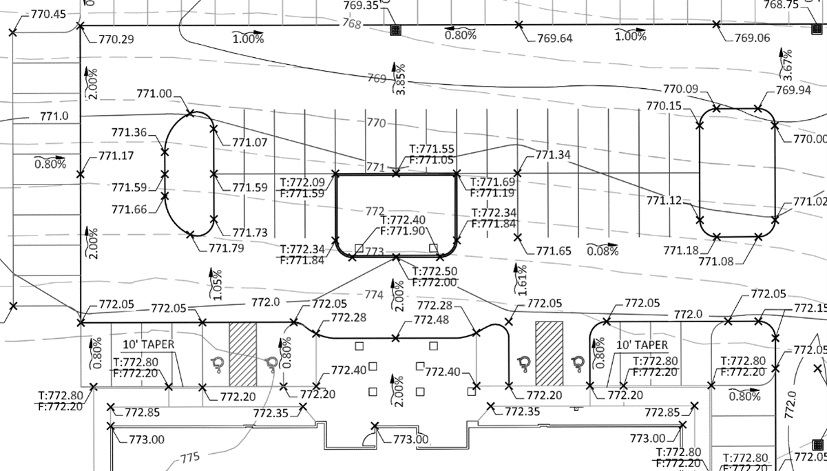
In our example shown above, the contours were drawn in later to show the general slope of the parking lot. The slope arrows provide some faint clues on how the water is moving. This one took some time to get right.
3D Lines
When doing curb, the elevation of a line changes. We first need to plug in the numbers from the plans, then fix issues that are obvious.
If there are things that do not make sense, we need to run a request up the ladder and get more information.
In our sample project, the slopes in the ADA parking areas are out of spec. This is not an issue; we check the percentages and make them right. If they do not fit, we need to talk to someone. A quick once- over of an engineer’s surface will not catch these small details.
There are a lot of things we can do with these lines. Offset the flow line to get top back of curb, even extend that line for staking. This requires us to create lines, which cannot be done from a surface found in the original CAD.
Points and breaklines
I have always used points to create an absolute elevation. Think of the rim of a storm grate.
Points are used by our clients to layout improvements.
Points are useful for curb radius points as well as footings and building corners.
We will do layout of light poles, playground equipment, electrical lines, and SES pads. The list is long.
Breaklines are used to make a surface respond the way you want it to. Triangle linking is indiscriminate and these lines make features look like the design. This could be from a simple ditch to parking lot flow lines.
They become the final tool to get things looking right. They are a necessary and sometimes frustrating tool. Too many breaklines and the surface is strained, too few and details get lost.
Summary
In order to use a surface made by someone else, the above issues would need to be addressed. It takes longer to take things apart and put them back instead of doing it right the first time. Cheap data uses information that is not correct. A few checks and it lands on your site. Instead of a surface you have a minefield, not knowing where the bad spots are. There is still a culture of “fix it in the field.”. This does happen when provided with too little information, but it is the rule when dealing with marginal work from less -experienced model builders.
I, in no way, am faulting engineers for this. Any surface made by them is for a different purpose. It is the job of the model builder to get inside the plans and understand the site from a singular point of view. Will it perform as intended? Years ago, I wrote an article in Machine Control Online Magazine. The title was “You Pay Us to be Nervous.” You just cannot do a good job in a couple hours.