In the early days of machine control, we were lucky to have everything working at the same time. Hardware and firmware needed a lot of work and seemed to get worse with upgrades. Those of us who got past the tough times now have keen insight into how to trouble shoot hardware, firmware, and data models. When the bugs got worked out, we started to look ahead and really leverage the technology. In this installment, I will go over what we are able to do with data for subdivisions. Many of these ideas come from clients wanting to do more with their gear and trying to get the best from our modeling capabilities.
Basic Subdivision Models
It all starts with a model that represents the streets, pads, and common areas to required finish condition. By this I mean that depending on the scope, it may be street paving and curbs or rough grade if all they are doing is dirt.
The difficult thing about subdivisions is that we are working on a lot of corridors and intersections, and they all need to work together to make water do what we need for homeowners to drive safely. Nobody wants to scrape their spoiler on a steep dip or go airborne on a bump. These details should be sorted by the time the plans get to us but there can be issues that need addressing. We can catch issues during data production and let our client and the engineers know before a bad idea gets paved. Here are basic subdivision deliverables.
• Streets to finish, subgrade, or gut section (more on that later).
• Streets need to be done to plan/profile and template. We then drop them on plan view and clean the intersections.
• Pads to their finish grade condition. This may be flat, sloped or stepped for walk out basements.
• Common and retention areas to finish. We may also include a subgrade for retentions if there is a liner or filler material to go in. This could also be sod.
• Some large lot sites do not get graded pads. We usually do a 3:1 cut/fill slope to native so the custom home can grade as they see fit.
• Utilities are optional and with housing, there are a lot of connections. This is a great data tool to use in the field.
For a long time, we were doing some cool stuff with housing. After the 2008 crash, the market came to a speeding crawl causing many of the forward-thinking people in the field to pursue different areas, and some never got back to doing houses. When things started to bounce back around 2012, housing was new to many people. Yes, we are still moving dirt but some of the tricks we used in the past to make things faster were new to the fresh crop of housing contractors.
The Gut Section
Many times, we are asked to build several different models for the streets. With top of native and possibly subgrade surfaces, we also build gut section models. This allows the contractor to rough grade for streets leaving room for the utility spoils to be used in place to get the job to top of native.
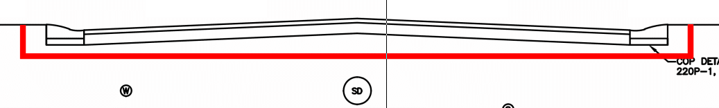
The red line represents the gut section. After the utilities are installed, the remaining dirt will be used to get the job to top of native. Note there is subgrade as well as paving shown here. Using this approach reduces the movement of dirt as well as speeding up the process.
Haul Roads
When doing large cuts and fills on a site using scrapers or haul trucks, good smooth roads are beneficial. Here is how we look at and build haul roads.
• Look at cut/fill regions. Connect large cut to fill areas to make transfer easier.
• As much as possible, use existing streets and connect them with custom haul roads that connect to the design profile grades so you are building road subgrade at the same time you are hauling.
• Produce machine control models for the haul road/finish street combination.
• Grade these on a regular basis to optimize the speed of equipment and keep stated cycle times.
• The roads often run through areas that are to be restored native or park areas. Verify you can do a topo of the area for returning to previous after your work is done.
• Sometimes we build a road on existing ground conditions to start. As dirt is added/removed, the crews dial down/up to grade the road. We have done three or four iterations of the profile for big cut/fill jobs.
The reason for these proposed basic rules is that many jobs were looked at like a site. Regions made from large cut areas and moved to large fills. When you utilize the finished street alignments you get a head start on them as well as leaving most of the pads alone to be completed early so crews can stay busy.
Early Utilities
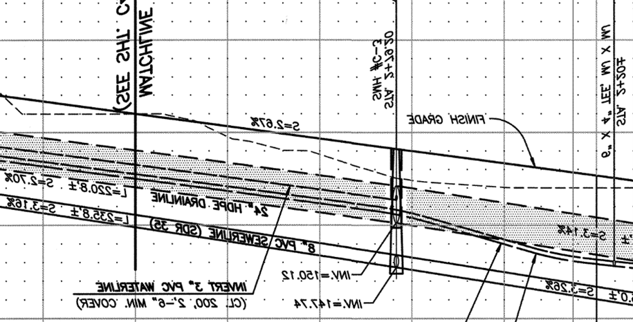
Installing underground utilities requires a bit of planning but has become a real time saver in the field. We are now working on sites that are expensive to build on because of the large amounts of required dirt moving. None of us want to dig more than necessary so I got an idea. Why not install underground utilities before all the fill is done? Apologies for the poor example but I just could not find a recent set of plans with huge fill.
• Let us assume the minimum cover for the lines is three feet.
• In large fill areas, there may be 20 feet of dirt that needs to go in.
• We run calculations on areas where the storm and/or sanitary have more than three feet of cover.
• We build a “utility base fill” model.
• This model gives you three feet of fill in the utility areas.
• You can now do minimal fill, trench, and place pipe.
• When complete, the fill goes on as usual with compacted lifts as required in the engineering reports.
This works for different projects, not just housing. When you encounter large fill areas, keep this in mind. When using multiple surface models, be sure everyone is on the correct page. Things can get out of control quickly when there are mixed messages in the field. This is where the field person responsible for loading machines and data collectors are required to be on top of things.
When spring rolls around, road construction gets into full swing. Road contractors have been early adopters of technology and continue to drive the development of new applications and equipment. Among them are laser augmentation for vertical accuracy and the automation of paving and curb machines. To improve efficiency, contractors should use technology wherever possible. This includes preparation of dirt grades and the application of subgrade materials.
Optimizing Standard Road Subgrade Construction Techniques
When working with a site, it is easy to “dial down” the surface in order to grade to the top of dirt, compacted subgrade, and rock. This vertical offset works well, even though it just lowers the entire site to the set amount.
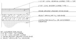
This drawing shows three (3) layers that can be installed using at vertical offset. With a well prepared subgrade, it is possible to pave using sonics and obtain good results in a basic parking lot.
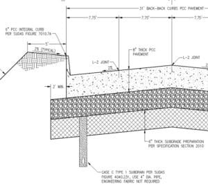
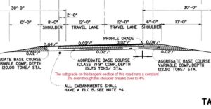
For many road jobs, the subgrade is easily set with vertical offsets. A typical road design for urban rehabilitation work is one example. Here we see top of dirt and a prepared native subgrade that can be done with vertical offsets.
The subgrade extends beyond the road/curb finish. To make this easier to model, just the finished surface can be built. The equipment operator can run the blade down the road section and use sonic and cross slope, or a horizontal machine offset to pick up the additional two feet.
Techniques for Achieving Extended Road Subgrades
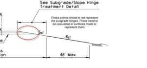
Another layer of difficulty is added where side slopes are built into a roadway. The subgrade hinge represents the intersection of the side slope and the projection of the subgrade. It is shown in this drawing inside the red circle. Refer to the video for a better understanding. There are two ways to accomplish the production of the subgrade hinge, office calculations or field adjustment.
Office Calculated Subgrades Software programs can build the subgrade for roads with extended hinge points. It requires the data builder to build “another road”, adding time and complexity to the project. The result of this work is a new surface that represents the top of dirt grade where the subgrade and side slopes can be graded as one surface.
Often there is not enough time, or the data builder may not have learned the process. The field crews can establish the hinge point by the following method.
Build the road to finish grade. Establish the side slopes and begin grading them. At the same time, machines working the driving lanes can check the progress of the dirt grade. The machines on the driving lanes can dial down to the top of dirt, as long as they do not break over to the side slopes. Using horizontal offsets, the driving lane machines can work with those on the side slopes. The hinge point will result from their work. My YouTube video will clarify this.
Navigating the Complexities of Multi-Layer Road Subgrades
Often, roads are done in two complete stages; from actual bidding to execution. The earthwork is part of one contract, and base and finish is on another and comes later. We see this in areas that have limited work due to weather constraints. In these areas, subgrades may not follow the cross slope of the main lines in super elevated sections. We have seen tangent section subgrades that are different cross slopes than the paving. Conditions like these require a full office build of the subgrade, as it changes cross slopes at a different rate than the paving.
A complex road subgrade benefits from machine control. It also requires the production of at least one additional surface for the subgrade. The additional work is rewarded with a better product produced in a shorter amount of time.
Precision in Locating Compacted Hinge Points for Road Subgrades
When building a road subgrade model, we know the finished location of the hinge point in 3-dimensions. If you don’t make all subgrades in the model the hinge point, the surface you are working on may not be called out. I will cover a work around in detail.
When this information gets into the field, the dirt either needs to be laid flat to compact to grade or compacted high to trim. With expensive subgrade materials and expensive geo-textile mats, there is no room for error. Here are some methods we employ to make this work.
Essential Practices for Trimming Road Subgrades to Perfection
When you get compaction on select fill in a subgrade planned for trimming, the trim amount is often not specified. We have seen times where you need to overbuild to 5-hundreths and trim, but this is the exception. Here is what we do:
Run tests with real world natural conditions, meaning the OG may compact more in some areas. Test compaction amounts of the select fill and adjust if the material spec changes. A close relationship with the supplier will help here. The biggest change we see is moisture. Some fills will respond to high moisture content poorly. Once everybody is happy with the testing, closely monitor the first few instances to confirm. Stringless trimming is the way to go here.
The road model is also what was used to produce the subgrade model. Trimming fill is cheaper than grinding concrete, so this is your first check of the roadway model. Any adjustments made in the field need to go back to the model builder so that the finished paving can reflect updates. We see this mostly around bridges, drainages, and tie ins.
A trimmer needs the same setup quality a paver does. I have seen trimming crews run a bit fast and loose with subgrades as the stakes are not as high. Watch closely.
Strategies for Managing Multiple Road Subgrade Layers
It is possible to model all the subgrades in a road job. We have all seen, and marveled, at a well compiled model that allows us to quickly create a model of a surface. Material types change during a project as well as thicknesses. We want to keep up with the changes, but it is easier to dial down from finish and intercept the side slope.
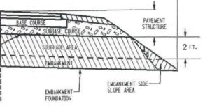
Here we see a paving section where multiple materials intersect and even stop short of the side slope. The called out “Embankment Side Slope Area” is drawn differently than it will be graded. Most will run the subgrade and embankment to the side slope.
In building this model, there are multiple hinge points. The best way to address this is to get the side slope close to right and run the subgrades out to the hinge. There are some precautions that you need to be aware of:
The BIGGEST issue that needs to be addressed are correct slopes and daylight lines. Be sure you have a tight ground model to model. Only then can you rough cut the side slopes to get the hinges right with less material use.
Compaction of embankment will be a moving target. Watch compaction of different soil types.
Don’t think you’re wasting your time building different subgrades. They make sense for a lot of jobs.
When automating paving, we will build a track grade model that sometimes changes the hinge point during construction. A final model is used to get the slopes back in line after.
The building block of a surface used in civil and architectural 3D modeling is the TIN (Triangulated Irregular Network). We will go over its definition, rules, and tips for making this format perform. Let’s get started.
The TIN surface
Definition
A TIN (triangulated irregular network) is the format used to transmit spatial ideas into something that can be transferred to the ground for civil (and architectural) work. A TIN consists of triangle definitions that have x, y and z coordinated for each of the three points. The triangles do not overlap and share common intersection points.
The triangles can be any configuration and size. The only limitation are the three sides. The triangles are all flat planes (NOTE: this will be important to remember later). When generating a TIN, you will often see some large triangles, some with long edges and some with very small edges.
The vertices of the triangles are generated from 3D elements provided from the following three elements you will create. They are 2D lines (contours), 3D lines and points. The vertices are made up of how far apart they are interpolated and elevations assigned to these elements.
TIN Faces
The connected 3D points that make up the TIN are TIN edges. They should not be looked at as lines but instead as a visual representation of the edge of the flat triangle. This will tell you where the grade breaks to the next triangle are so the surface will perform the way you want.
TIN Breakover
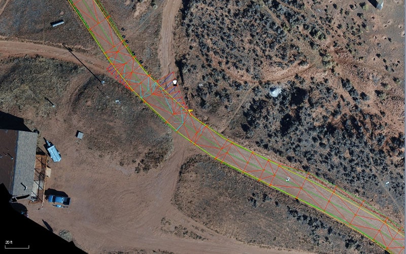
The TIN Breakover refers to the angle from one flat triangle to the adjacent one. This is important to mention because if the angle is too great, you can add more points therefore generating more triangles and softening the severity of the angle.
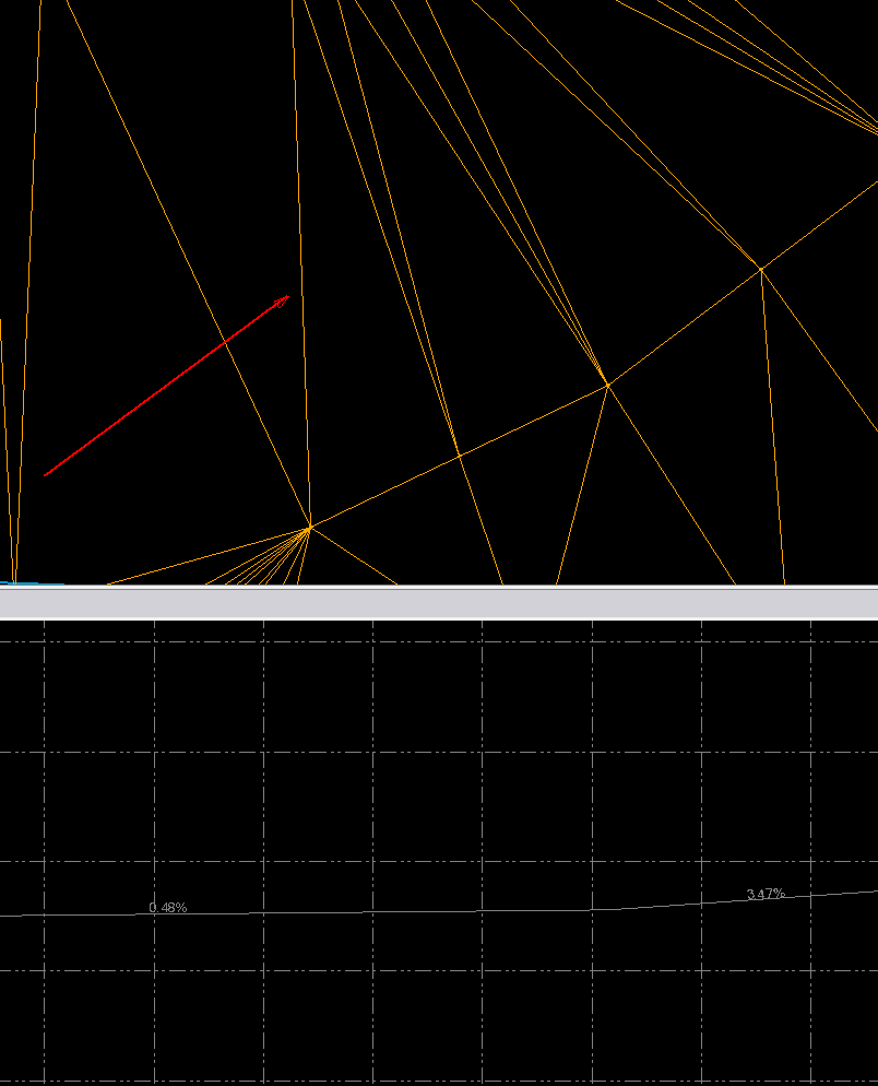
In this example, the slope between these two triangles goes from .48% to 3.47%. Smaller triangles have been added to smooth their transitions.
You may not always want smooth transitions. Starting with the top or toe of a slope, you will want to hold a 3:1 ratio as it flows to a flat bottom. In this case, be sure to add enough data points so there are no errant elevations in that area. This will be covered more later.
TIN Density
If 10 is good, 100 is better, or so we used to believe about surface triangles. The short answer to TIN density is to add just enough to make the surface do what you need it to. Currently, the advantage is that faster computers and segmented TIN handling have made things better. Field firmware can break up surfaces to load just the area you are working on and not the entire file.
Over the years I have come up with guidelines to help users get closer to the balance of surface, size, and performance:
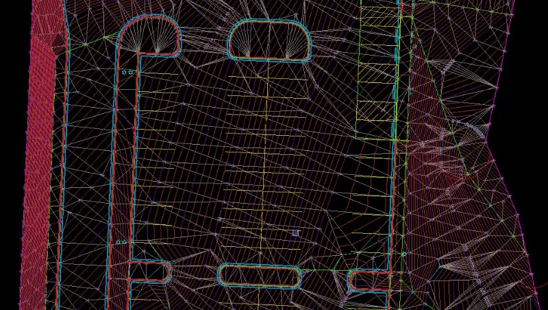
Try and make all the triangles (in an area) the same size. This insures smooth edge transitions and helps large grader blades operate better. In this screenshot there are similar sized triangles in a parking area. You will need to add more triangles as things warp and not just slope like this example. Be sure to add where needed.
For this example, triangles need to be added because of the arcs on the parking islands and the changing slopes. These elements require that water is pushed away from the parking curb into the drive area. Never assume that the number or appearance of triangles indicates the quality of a surface. It’s just a starting point. We are looking for a surface that does what is needed for that job, which changes all the time.
Do not confuse TIN density with the actual point elevations you assign. Add points where the grade must change. Look at a surface like you are laying out points to grade to. A blade will connect those dots. That is where TIN density comes in.
Density Settings
Software can densify surface points when it makes the TIN. There is no need to add these points during the line/point process as they are densified in the settings when it
is time to make the TIN. When working on a surface, we will not add additional points, so we can see the work we are doing. When we like the points/lines we have made, then we will increase point density. This increase in points will address the issues I have been discussing like breakovers and detail areas.
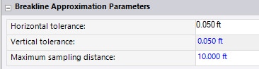
Business Center addresses this in the settings as the maximum sampling distance. I will also address the tolerance items in a bit.
Carlson allows the distance to be turned on and off while keeping the setting.
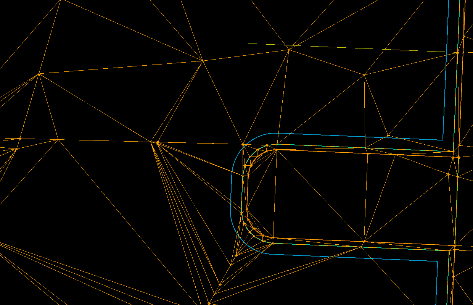
The horizontal and vertical tolerance settings refer to the middle ordinate of the cord that represents the arc. That distance is the maximum a chord line can be from an arc.
The red line is the TIN line and the green is the 2D arc. That setting will adjust the space shown here.
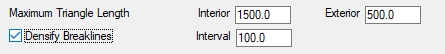
A good start for setting the distance number is 10 feet for small sites up to 10 acres. We move to 20 feet when things get larger than that to keep a good surface size. There are instances where you will need to adjust this but this is a great place to start.
Surface Review and Detailing
When you have a surface that looks good to you there needs to be a way to check it. You need to look at the appearance as well as the performance. Let’s first look at appearance.
Surface Appearance
To get paid at the end of a project, an owner must be satisfied with how the job looks. We have all seen poorly performed jobs that look great. Commonly the issue is that the performance faults appear after a crew has left an otherwise good-looking job. Depressions and bird baths in parking lots. Incorrect paving base depths and respreads thicknesses all take time to manifest and tarnish the overall appearance of a job.
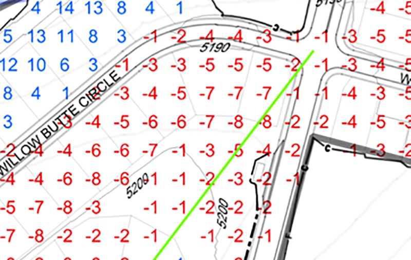
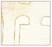
The easiest way to see how a surface looks is to contour at a tenth of a foot interval. Subtle grade changes become obvious and draw your attention to the areas that need attention. This image shows good transitions and will not surprise a fast driver at the entrance.
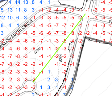
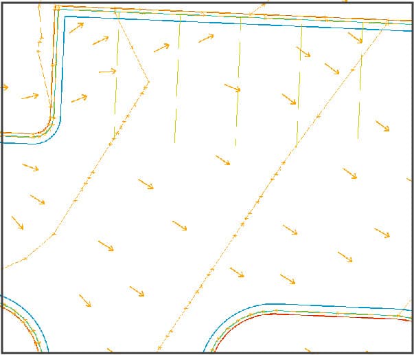
To verify how the water is going to flow, turn on the slope arrows for confirmation of how water will flow when it rains and snows.
Take a close look at the parking stall in the northwest corner. There is a grade break at the south end of the parking stripe moving water to the northeast and then joining the sheet drainage to the southeast. This looks a bit odd but keeps the water moving out of that corner.
You also need to look at drainage areas. These areas need to keep water moving in the right direction and can also be used as common areas and playground facilities. The potential use of drainage areas varies without a lot of ADA requirements for slopes due to being primarily drainage. Be sure to review contours and slope arrows for correct directions.
Surface Performance
Now that the surface looks good, it’s time to verify the performance. At this point contours are not necessary, but I like to keep slope arrows on while moving around the project. I will go over this in the accompanying video. When reviewing a job at this stage, these are the things I look for.
Building
We usually don’t do much in data for the areas outside a building. When concrete is installed and grading is performed around a building, the GPS survey signals are blocked and the work is done with smaller non-controlled machines. In any case, make sure there is drainage outside the building envelope per plan. We often see 5% slopes for dirt outside the building.
Hardscapes
Any sidewalks outside the building as well as common area sidewalks need to be at no more than a 2% cross slope. We have some clients that have us slope to 1.5% for a margin of error to not exceed the maximum. Trail looking sidewalks are common in drainage and park areas, and sometimes have vertical alignments associated with them. These types of mini-road jobs need to be looked at where the alignments and sidewalk are treated like a roadway. In my experience, this is the best way to work through them. It may take a bit more time but it’s worth it.
Paving
After reviewing the contours and slope arrows we can confirm the surface will drain. This is the time to make sure the paving is done correctly. A big debate in our industry is the production of subgrades. I don’t mind having software build subgrades for a takeoff, but I don’t like to use them for production. The crossing lines and vertical jumps in the surface can affect a blade as well as not being sure that they are in the right place. A few inches thick paving on a takeoff is okay but will result in phone calls if it makes its way to the model.
We recommend dialing down in the machine or rover to get to subgrade. The fact is you must have the presence of mind to either load the correct surface or dial down. Either decision takes thinking it through and attention to the details. We don’t feel we need to spend our client’s money for building subgrade surfaces when field dial downs are better. Here is why. I can dial down to get to top of dirt in a parking lot, then pick the back of curb line and do a 3-foot offset to get to back of curb with room for the curb machine. Focus the 3D on the other blade tip and the parking lot slope will be projected to the back of curb. That surface cannot be made easily in the office and is quick in the field to accomplish.
There is a process we go through when producing site data and is tweaked by each of our engineers to suit them. Come up with your own process and stay with it. Productivity increases when you know what you have done and what comes next.
UPDATE – AUGUST 2020
I have received many questions regarding TIN surfaces after this article was published. There is a lot of confusion regarding how a surface looks on the screen and how it performs in the field. Here are some tips.
Consider the Use
The biggest question is, “What will be making the grade in this area of the project?” When you are near buildings in tight areas or a small retention, a grade setter will be there to call out or establish grades to be done conventionally. In a larger area where a blade will fit, machine control will be utilized.
When working in a constrained area, think about what you need to do for water to drain and sidewalks to meet code.
In this image we are looking at a sidewalk next to a building. This will be graded and leveled by a skid steer and laid out by hand. Here is what will happen for data prep in this area:
The sidewalk will be modeled at finished grade. In this case, we will go with a 1.5% slope in case it does not grade. We will remain under the 2% ADA max.
There could be trouble if the curb is not correct because there needs to be a straight grade from the curb to the building entrance. Pay special attention to curb layout here.
The ADA ramp needs to be set in the collector so the field has this information for layout.
Get some 2D layout for the alternating sidewalk/paver layout.
The best thing to do for sidewalk layout is to calculate the center point of the radius and let the field run line to get the curve correct.
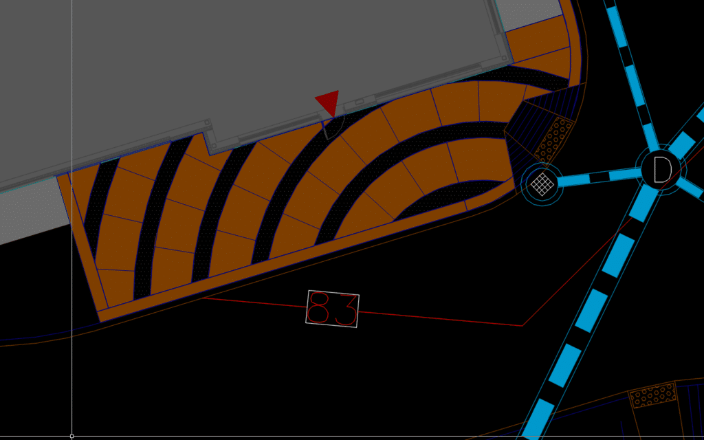
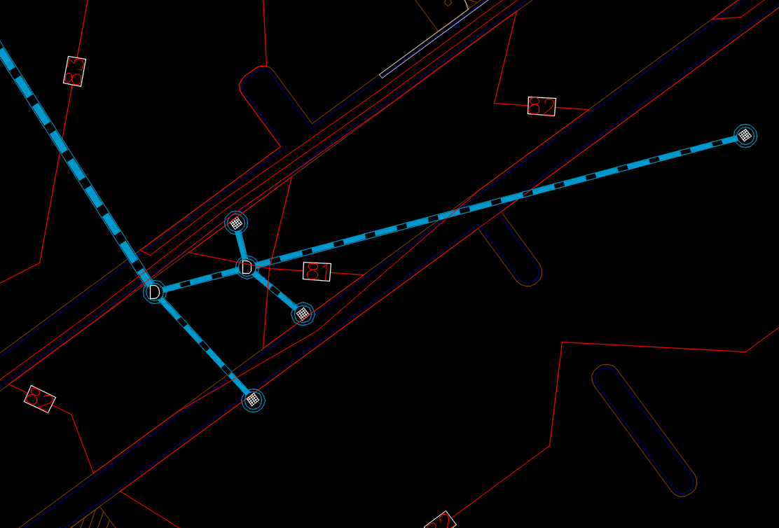
In this part of the job, things are getting more open and easily done with a grader. Here is the approach:
The entry road is where you see a low point at 81 feet and storm structures. Add a vertical curve to make sure this grades well.
The peninsulas in the parking lot may be modeled depending on client preference. If we put them in, they will be manual across the curb bump but some like to see them in the model.
The isolated islands in the parking lot get ignored, so the blade makes a good surface for paving.
Think in terms of the blade, 10 to 14 feet of material will be graded and too many breakovers make the system jumpy.