Being a non-CAD program, the developers of Trimble Business Center were able to create something entirely new and change things they did not like about CAD, (things none of us like about CAD) with a fresh approach to data creation and manipulation. The roots of CAD have always been the creation of a 2D set of plans. The 3D first approach has become an advantage for TBC. Below are the things that make it function.
JUMP TO SECTION
The Interface
Commands
When I want to streamline the data process, a well-written command will make life easier. However, automation of a process comes with a price and sometimes you get results you do not want. When trying something new or potentially harmful, do a save and give it a try. Trimble likes to build a left to right icon structure to streamline processes. My last article discussed this and the option of custom command ribbons. I will not repeat it here so check it out.
Enter Rockpile Solutions
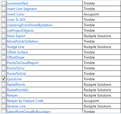
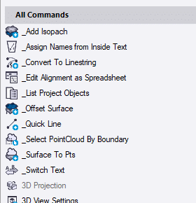
I like the fact that I can use one platform for everything from data to point clouds. The list of modules is extensive and now with the combination of geospatial and construction the depth is incredible. You may never need the full power of the program, but I cannot count how many times I needed to solve an issue and had the horsepower to do it quickly. This very thought is what should motivate you to scroll through the available commands to see what you are able to do.
Data Prep Components
The forums have been buzzing with activity regarding Civil 3D files and TBC. The best way to get files from Civil 3D to TBC is to have C3D. The format is updated every three years and objects are best dealt with in native programs. Yes, it gets expensive but so does not having all the information you need. Autodesk makes a lot of proprietary formats, as does Trimble. That is the best way to get the functionality you need within the confines of your program and development.
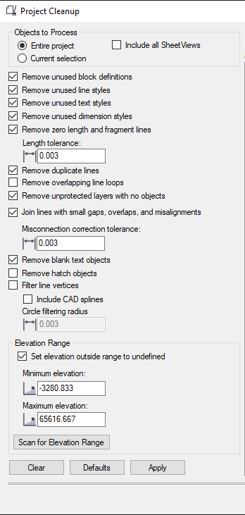
There are a lot of tools in Project Cleanup that will help with CAD files that have the AECC objects converted to CAD objects. If you do not have the file in that configuration, there will be less information on the screen to work with.
The selections are self-explanatory. I will sometimes try a few different settings and undo the last file cleanup. In other words, I will uncheck some items that made a bigger mess than they fixed. Try various settings on your imports to get a feel for what you are looking at and why it may have gone sideways.
Now that we have a decent bunch of lines to work with, let us elevate things.
The Linestring
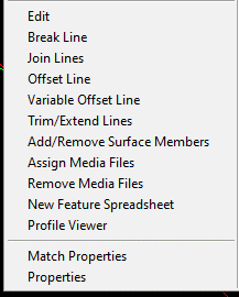
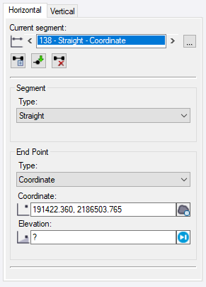
A right-click on a linestring brings up a lot of options. I will open the Edit command and discuss the details of the object. The most important thing to note are the Horizontal and Vertical tabs. Here is how to view these tabs.
- Horizontal change to a line will affect the Coordinate Geometry, (COGO) changing what you see on the plan view of the object. Straight segments and curves are made and changed here.

- Elevations can be changed in the middle of a long straight line in a place where there is no horizontal instruction. This gives you great flexibility.
- There are other editing features for adding and removing segments and instructions.
- You can also bring up a profile view to watch your vertical work in real time.
It takes a bit of time to work out a process here because there are many tools to choose from and learn their capabilities. Here is my method.
- Get the line connected and any loops removed. Sometimes I must follow the line with the cursor to verify this.
- Once I have a 2D line to work with, I make sure the color is good and it is on the right layer. I will often do the first round of work on the native CAD layer then move it to a 3D data layer. When I turn off the data layer, I find a lot of lines in the same location that could make a mess. It is not good to always rename an entire layer to a 3D layer; you may want to migrate individual lines.
- I now add the vertical component. I mentioned the profile view to aid in real time review. I will give the line a single elevation that is close to the middle height of what I am doing, this avoids the balance of a line at zero with your current work a lot higher. Set elevations with CAD text and/or the pdf under the linework.
- I will perform a review of this process in a video to help you better understand.
2D Lines
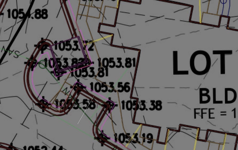
In the following point I am referencing contours that need to be included in a surface. They are at a single elevation making them 3D but we call them 2D. I have learned to live with it. TBC has some great tools for converting zero elevation lines to contours and they are easy to use. I try to get everything elevated then start breaking lines and deleting segments I do not need for a surface. This process seems to work best.
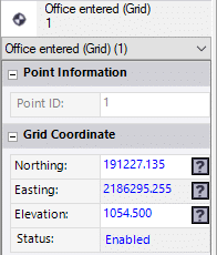
Points
Many do not use points as much as they should. Points are easy to create and a big help when you want an exact place at a particular elevation. Here are the obvious and lesser known uses for points.

- Top of covers for water and sanitary
- Corners of wing walls, SES pads, and handicap ramps
- Corners and direction change for pads and blowups
- Points along flowline of storm and sanitary to aid in digging trenches
- Striping layout
- Light poles and common area equipment like benches and play structures
- PC, PT and radius points for curb layout
Do not forget point collection in the field to return to the office for processing and storage.
- Daily as-built shots for all phases of work
- Utility lines and structure shots
- Long occupation shots of the saw cut and connections for drive entries and deceleration lanes
- Quick topo of retention areas to verify volume calculations
When combined, the three key items (2D lines, 3D lines, and points) become a surface for a quantity takeoff or field data. Make sure each item is a separate task and are correct individually before combining to make a surface. It will relieve the process of errors.