The building block of a surface used in civil and architectural 3D modeling is the TIN (Triangulated Irregular Network). We will go over its definition, rules, and tips for making this format perform. Let’s get started.
The TIN surface
Definition
A TIN (triangulated irregular network) is the format used to transmit spatial ideas into something that can be transferred to the ground for civil (and architectural) work. A TIN consists of triangle definitions that have x, y and z coordinated for each of the three points. The triangles do not overlap and share common intersection points.

The vertices of the triangles are generated from 3D elements provided from the following three elements you will create. They are 2D lines (contours), 3D lines and points. The vertices are made up of how far apart they are interpolated and elevations assigned to these elements.
TIN Faces
The connected 3D points that make up the TIN are TIN edges. They should not be looked at as lines but instead as a visual representation of the edge of the flat triangle. This will tell you where the grade breaks to the next triangle are so the surface will perform the way you want.
TIN Breakover
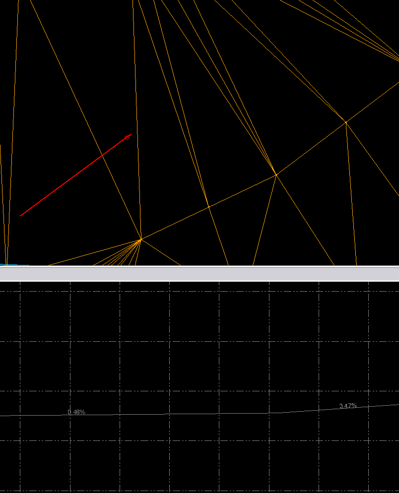
In this example, the slope between these two triangles goes from .48% to 3.47%. Smaller triangles have been added to smooth their transitions.
You may not always want smooth transitions. Starting with the top or toe of a slope, you will want to hold a 3:1 ratio as it flows to a flat bottom. In this case, be sure to add enough data points so there are no errant elevations in that area. This will be covered more later.
TIN Density
If 10 is good, 100 is better, or so we used to believe about surface triangles. The short answer to TIN density is to add just enough to make the surface do what you need it to. Currently, the advantage is that faster computers and segmented TIN handling have made things better. Field firmware can break up surfaces to load just the area you are working on and not the entire file.
Over the years I have come up with guidelines to help users get closer to the balance of surface, size, and performance:
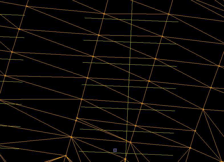
- Try and make all the triangles (in an area) the same size. This insures smooth edge transitions and helps large grader blades operate better. In this screenshot there are similar sized triangles in a parking area. You will need to add more triangles as things warp and not just slope like this example. Be sure to add where needed.

- Do not confuse TIN density with the actual point elevations you assign. Add points where the grade must change. Look at a surface like you are laying out points to grade to. A blade will connect those dots. That is where TIN density comes in.
Density Settings
Software can densify surface points when it makes the TIN. There is no need to add these points during the line/point process as they are densified in the settings when it 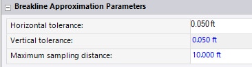
Business Center addresses this in the settings as the maximum sampling distance. I will also address the tolerance items in a bit.
Carlson allows the distance to be turned on and off while keeping the setting.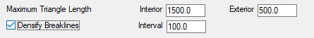
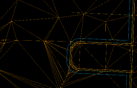
The horizontal and vertical tolerance settings refer to the middle ordinate of the cord that represents the arc. That distance is the maximum a chord line can be from an arc.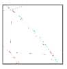
The red line is the TIN line and the green is the 2D arc. That setting will adjust the space shown here.
A good start for setting the distance number is 10 feet for small sites up to 10 acres. We move to 20 feet when things get larger than that to keep a good surface size. There are instances where you will need to adjust this but this is a great place to start.
Surface Review and Detailing
When you have a surface that looks good to you there needs to be a way to check it. You need to look at the appearance as well as the performance. Let’s first look at appearance.
Surface Appearance
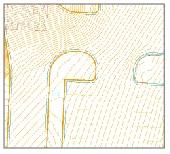
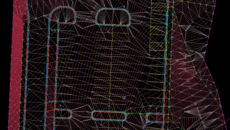
The easiest way to see how a surface looks is to contour at a tenth of a foot interval. Subtle grade changes become obvious and draw your attention to the areas that need attention. This image shows good transitions and will not surprise a fast driver at the entrance.
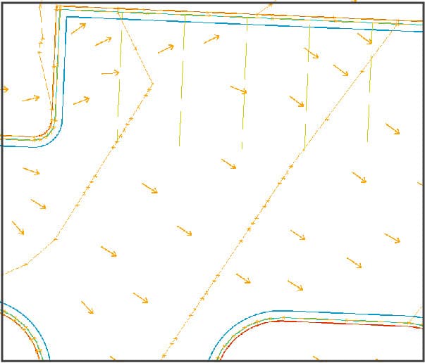
Take a close look at the parking stall in the northwest corner. There is a grade break at the south end of the parking stripe moving water to the northeast and then joining the sheet drainage to the southeast. This looks a bit odd but keeps the water moving out of that corner.
You also need to look at drainage areas. These areas need to keep water moving in the right direction and can also be used as common areas and playground facilities. The potential use of drainage areas varies without a lot of ADA requirements for slopes due to being primarily drainage. Be sure to review contours and slope arrows for correct directions.
Surface Performance
Now that the surface looks good, it’s time to verify the performance. At this point contours are not necessary, but I like to keep slope arrows on while moving around the project. I will go over this in the accompanying video. When reviewing a job at this stage, these are the things I look for.
Building
We usually don’t do much in data for the areas outside a building. When concrete is installed and grading is performed around a building, the GPS survey signals are blocked and the work is done with smaller non-controlled machines. In any case, make sure there is drainage outside the building envelope per plan. We often see 5% slopes for dirt outside the building.
Hardscapes
Any sidewalks outside the building as well as common area sidewalks need to be at no more than a 2% cross slope. We have some clients that have us slope to 1.5% for a margin of error to not exceed the maximum. Trail looking sidewalks are common in drainage and park areas, and sometimes have vertical alignments associated with them. These types of mini-road jobs need to be looked at where the alignments and sidewalk are treated like a roadway. In my experience, this is the best way to work through them. It may take a bit more time but it’s worth it.
Paving
After reviewing the contours and slope arrows we can confirm the surface will drain. This is the time to make sure the paving is done correctly. A big debate in our industry is the production of subgrades. I don’t mind having software build subgrades for a takeoff, but I don’t like to use them for production. The crossing lines and vertical jumps in the surface can affect a blade as well as not being sure that they are in the right place. A few inches thick paving on a takeoff is okay but will result in phone calls if it makes its way to the model.
We recommend dialing down in the machine or rover to get to subgrade. The fact is you must have the presence of mind to either load the correct surface or dial down. Either decision takes thinking it through and attention to the details. We don’t feel we need to spend our client’s money for building subgrade surfaces when field dial downs are better. Here is why. I can dial down to get to top of dirt in a parking lot, then pick the back of curb line and do a 3-foot offset to get to back of curb with room for the curb machine. Focus the 3D on the other blade tip and the parking lot slope will be projected to the back of curb. That surface cannot be made easily in the office and is quick in the field to accomplish.
There is a process we go through when producing site data and is tweaked by each of our engineers to suit them. Come up with your own process and stay with it. Productivity increases when you know what you have done and what comes next.
UPDATE – AUGUST 2020
I have received many questions regarding TIN surfaces after this article was published. There is a lot of confusion regarding how a surface looks on the screen and how it performs in the field. Here are some tips.
Consider the Use
The biggest question is, “What will be making the grade in this area of the project?” When you are near buildings in tight areas or a small retention, a grade setter will be there to call out or establish grades to be done conventionally. In a larger area where a blade will fit, machine control will be utilized.
When working in a constrained area, think about what you need to do for water to drain and sidewalks to meet code.
- The sidewalk will be modeled at finished grade. In this case, we will go with a 1.5% slope in case it does not grade. We will remain under the 2% ADA max.
- There could be trouble if the curb is not correct because there needs to be a straight grade from the curb to the building entrance. Pay special attention to curb layout here.
- The ADA ramp needs to be set in the collector so the field has this information for layout.
- Get some 2D layout for the alternating sidewalk/paver layout.
- The best thing to do for sidewalk layout is to calculate the center point of the radius and let the field run line to get the curve correct.
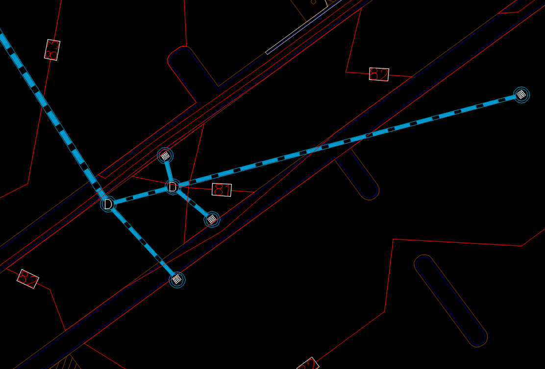
- The entry road is where you see a low point at 81 feet and storm structures. Add a vertical curve to make sure this grades well.
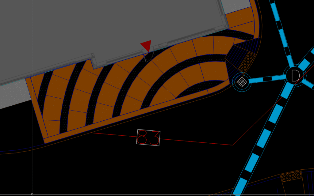
- The peninsulas in the parking lot may be modeled depending on client preference. If we put them in, they will be manual across the curb bump but some like to see them in the model.
- The isolated islands in the parking lot get ignored, so the blade makes a good surface for paving.
- Think in terms of the blade, 10 to 14 feet of material will be graded and too many breakovers make the system jumpy.