We need to strike a balance between a picture perfect model on the screen and a well-priced practical job that performs well. Nobody wants us or their model builder to make some infinitely detailed model that would be so dense it would slow down machines. Not to worry, I’ll include a video to show you what I’m talking about.
Now to the details.
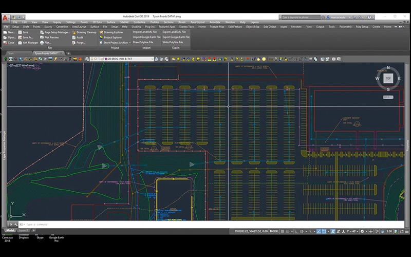
Parking lots
With the thousands of jobs we work on in any given year, parking lots are by far the most difficult. The reason is that the parameters are very specific but most plans lack sufficient information to accomplish this.
Plans should include:
All areas needing to drain correctly.
Slopes in common areas which need to support safe walking.
Handicapped parking spots requirements for slopes.
Grade breaks that will divert water to designed drainage structures.
In the past, the surveyor would blue-top spots from the plans and a grader operator would fulfill the above requirements. Now that we can do it digitally, it is important to check and verify plan intent so the blade operator can go full automatic in the field and get a good surface. When the data is not built correctly, an operator must field fix to make sure the rules are followed.
We are not going to go as far as running rainfall calculations to check engineering. We must however respect flow direction and grade breaks to deliver a smooth surface.
Here’s how:
Initially build the surface according to the plans. Fix obvious busts of three tenths or more.
Review the performance of the surface. I like to view slope arrows and create contours at a tenth of a foot which makes slope changes obvious and easier to fix.
Add breaklines to define the surface.
There is often a lot of time spent with small areas of a parking lot that are not working well. Experience will be the judge as to how much work it takes in order to meet the objective. Sometimes there just needs to be an extreme break over angle or varying slopes where you want a single one.
It is critical to remember how the surface is going to get from the screen to the dirt. A long grader blade is going to be making the undulations you have programmed into the file. Yes, the operator can rotate to make a narrower effective width, but it is important to consider this fact when building data.
Details
There are things we do that to me seem like a great way to increase speed and accuracy, improving margins. Here is a list of some the good and the bad:
Handicapped ramps. We can build a great handicapped ramp but I think common sense prevails. Machine curb will be run and the ramp cut out while the mud is still wet. We will give you linework so you know where to put the ramps but leave the curb full height.
Curb layout points. PC’s, PT’s, and radius points are a great way to layout hand built sections of islands and driveways. We will usually group the points by type so you can keep screen clutter down.
Saw cut line for turn lanes. When we get offsite plans, the existing road elevations may not be correct. Contractors will take good shots of the transition and send them off to us. We will build the entrance and propose changes in elevation where things aren’t right. We will forward that information to the engineers for approval.
Surface overbuilds. This is taking the outside edge of a surface three feet or more so equipment does not go out of design and need to reset wasting time. Newer control boxes are not a victim of this. If you are running older equipment then that’s OK. Don’t clutter up the screen with an overbuild if you don’t need it.
The take home message here is that data should look simple. The problem is that it takes a lot of work to make a simple looking surface. Machines and rovers have ten times the power and features than those from ten years ago. Use this to your advantage and leverage feature rich information. Your checkbook will thank you.
We have all been there. We come across a lot of numbers that need to be entered during a project. It could be spot elevations, alignment information or control. Life would get easier if we could just get the numbers from the page into our program!
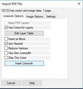
In this post, I will cover two approaches to accomplish the task. Carlson has a solution that is outlined in this video as well as a walk through in the article. One of our talented engineers, Jessica Dugger, let me know about an online service that is reasonable and highly accurate. Her experience was with a raster .pdf and resulted in a highly accurate conversion. Several characters were interpreted incorrectly, but that was an easy search and replace fix in Excel. I will use a vector sheet to show the process in Convertio.
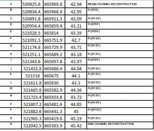
I used Bluebeam to breakout a sheet from a plan set for the demonstration. Nothing special, and this could easily be a table with a thousand points with equally huge coordinates.
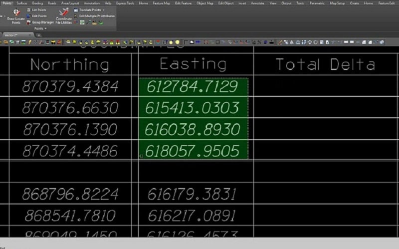
Here is the coordinate table I want to convert. Just as a test, I converted the entire sheet with plan and profile as well. It did a great job with the text and actually brought in the plan view areas as a .jpg. This may help as well for an image to send with an inquiry.
The coordinates came in fine. I can now do some quick Excel editing to make it easy for my software to recognize. I will use the letter for the point name and use the full description.
You will notice the flags on the numbers and the Point name “O”. They were text and I converted them to numbers. The “O” was text, I ignored it to keep it that way. The file was then saved as a .csv for use in any software. Here it is in Trimble Business Center:
The foot indicator came in as a question mark, other than that, the import was easy and quick. We use tools like this to improve productivity and give our clients better value by saving time in managing data.
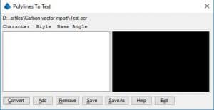
Carlson has a text conversion tool that does a good job. The prior example was really simple but the Carlson tool can come in handy with a lot of pages as it does not cost extra, or require you to be online for the conversion. We use it with jobs that require non-disclosure or are sensitive government work. Here is the process:
• Strip out the sheets to convert
• Bring them into Carlson as Linework
• Open the convert polylines to text command
• Create a new file name for the project
• Populate the characters you want to recognize
• Select and convert text.
Not to worry, I have done a complete screenshot video explaining the process below. The process is slow to set up and sometimes you will need to fix things in Excel doing a search and replace but overall the results will save you a ton of time!
As the construction industry becomes more dependent on technology, early innovators Marco Cecala and Tom Pastuszak from TOPS are setting the stage for the future. Read more from The American Surveyor’s latest profile article, “It’s All About the Data: A Visit to Take-Off Professionals.”
TOPS engineer Mike Tartaglia walks you through the simple and easy task of taking detailed information from a PDF and placing it to create a working model using the Point Offset feature in Trimble Business Center (TBC).
The TBC platform is field-to-finish survey CAD software to help surveyors deliver high-accuracy GNSS data, create CAD deliverables and leverage full data traceability throughout a project’s lifecycle. TBC can do everything from sites and roads to point clouds and photogrammetry.
With the New Year well underway, I wanted to take a look and review the advances and advantages of current imaging technology as it relates to creating surfaces from LIDAR and Photogrammetry.
It appears that the more things change, the more they stay the same. Several parts of this world have made great strides while many remain slow to progress.
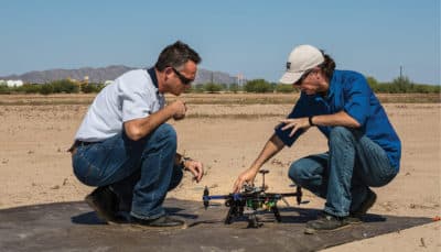
Drones
UAV platforms are cool, that is unless you have $38,000.00 in the air and it’s not responding to your request to come home. We need this device to do one thing; move a sensor in a predetermined pattern and image when requested and return safely for another use.
Prospective buyers have become focused on flight times, but the real number I always want to know is coverage and quality. A great camera with a proper lens can go high, fly for a short time, and get the accuracy we are after. Once you know all the variables, the questions you ask will change.
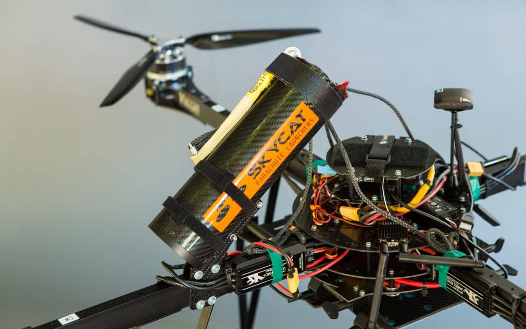
Multirotors have idled in regard to advancement. Good motors, precision GPS, and bigger more efficient batteries have allowed good flight times and safe operation. We use parachutes with our copters and feel comfortable sending them up.
Fixed-wing platforms are split into two distinct camps, hand and wheel launch. The small, quick wings cannot carry good cameras and data quality suffers. The larger platforms need wheels and smooth ground but offer the benefit of carrying a larger sensor for better images. There is crossover in these types including hand launch/belly or parachute landing; the blurred line is offering some possibilities.
I am hoping this next platform gets proven soon, I like where it is going. The VTOL (Vertical Take-off and Landing) plane holds promise. Lift like a copter then fly high and fast with a big camera for a long time. Like any other platform, power is always the issue, to remedy this, some makers are putting gas engines to be used as thrust motors and even generators. I think we will have something worthy by year-end.
Imaging
At this moment, the best solution for aerial topography is a full-frame sensor camera and a good lens. We can obtain good accuracy on a consistent basis. There are some improvements on the horizon that will help things.
When a drone flight is not possible due to regulatory restrictions, our trade partner Doug Andruik at Syn-Geo created a two-camera pod he puts on the strut of a Cessna and effectively does close-range photogrammetry with a full-scale aircraft. A great solution for large acreage or no drone zones.
We are all waiting until LIDAR becomes effective for use on a UAV. Several versions are out with fair accuracies and high price tags. Development is happening daily because of the great potential of the application. I’ll look at these and report as they become available.
Improving Accuracy
One of the best things to come along for improved close-range photogrammetry is precision GPS. The Applanix chips (Trimble) have made geo-referencing images more accurate and easier. When an image is correctly geo-tagged, post-processing is quicker and the resulting 3D information is more accurate. Combine this exacting geo-tagging and good images and accuracy get much better. This makes our fieldwork more efficient and the results in the office better. In my opinion, this is the go-to solution; for now.
Pix 4D is still the easiest post-processing software, my issue is the same data set run multiple times yields different results and residuals. As with any processing of imaging data, check to many ground control points to verify accuracy. UAS Master from Trimble is a robust application with the ability to fully incorporate precision GPS orientation from the Applanix chip. I use the software on a regular basis but am hesitant about training users. When you know how all the aspects of the program interface you can do some great things. When first learning post-processing, there are too many variables in the software to “just click a few icons” and get a result like in other applications. That Power can be a pain to use sometimes. Rumors are that there will be some easier workflows coming in future versions, I’ll keep you updated.
Contact TOPS for Accurate LIDAR and Photogrammetry Data
Right now the best way to get reliable, consistent data is to fly a full-frame mirrorless camera with a high-quality lens using a copter with an Applanix chip and post-process in the software of your choice.
Always collect a TON of control/checkpoints so you know how good the results actually are. We earn our money back in the office slowly going over data, cleaning up the point cloud modeling, and shipping the client a good surface.
Whether it’s for urban planning, environmental assessments, or infrastructure projects, TOPS photogrammetry services have proven to be an indispensable tool for professionals. Embracing such cutting-edge technologies ensures that we remain at the forefront of geospatial innovations, harnessing the best of what modern imaging can offer.
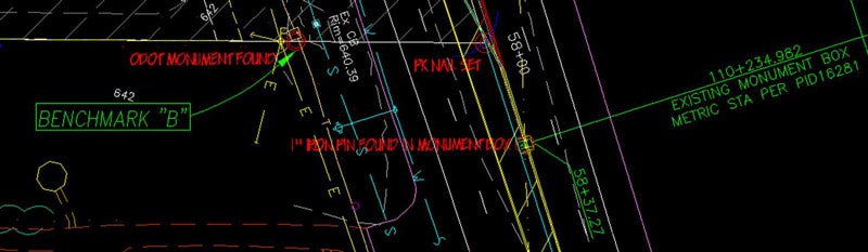
If you have never had the misfortune to deal with the difference between US and International feet, consider yourself lucky. When the issue presents itself, it can make things difficult to understand. No worries, the curtain will now be pulled back and the mystery solved.
First a bit of history, this will be abbreviated to keep you awake. The United States joined the Treaty of the Meter in 1875. It took the group 5 years to redefine the metric system, which made the length of the yard measurement used in the US at that time different from that used as the standard dictated in the Treaty of the Meter.
In 1960, the US changed the yard to .9144 meters exactly. This shortened the length of the new US Yard by 2 part per million. We will go over what this means in a moment, for now here is the conversion factors.
US Survey Feet vs. International Feet
One internal foot equals 0.999998 US Survey feet. To go from US feet to International feet, multiply US feet by 1.000002000004000008000016000032 (approximately) to get International feet. Yes, that’s five zeros followed by a 2 and a lot more zeros. In other words not a lot. To go from International feet to US feet, multiply International feet by .999998 (exactly).
The take home message above is two parts per million. In other words, if you were working on a 2 million foot long road, (378.79 miles) your error from end to end would be 2 feet. My point is that using either system will not affect your job. If you are using International feet and the job was surveyed in US feet, you will be OK. With exceptions, read on.
I will use a simple but powerful example to explain the issue. Our imaginary job has a corner point of N 2,000,000 and E 2,000,000. The surveyor localized in International and I build the job in US feet. The corner point I mentioned is the same coordinate value for both of us. It does not matter what coordinate system I use to localize the site with my rover. I am going to occupy the points staked by the surveyor. This includes our subject 2 million by 2 million coordinate. The job will fit and perform fine. I refer you back to the fact the difference in these two systems is 2 parts per million.
With the above information known to you, how can someone ever have a problem with the different systems? In a word; conversion. Let’s use the coordinates above. The plan notes read the job was built in International feet, we decide to make it US feet. Applying the conversion we get the following;
2,000,000 x .999998 = 1,999,996.00 In this example we can easily see the 2 parts per million. Our job is now 4 feet off to the north as well as the east. All you need to do is move the job and verify the rotation of the job from our 2 million, 2 million point. We always check at least 3 points. Here is the hard part to understand. You effectively shrunk the job, why won’t this affect the actual size of the site? I refer back to the 2 parts per million factor.
Let’s say you are on a big site, a big truck merchandise transfer facility off an Interstate highway. The job is a mile across. How will the job size be affected by the conversion? Here is the math.
1 mile, (5,280 feet) x .999998 = 5,279.98944 That translates to a hundredth of a foot over a mile. This difference is impossible to see on paper, or in the field.
What do you need to do? Here are the guidelines for success in international feet to us survey feet conversion;
Try to use the native units the job was designed in.
Never convert units, just know what you have and what coordinates the site was localized in.
Make a note of at least 3 points that you can find on the CAD file and the site. Refer to these and verify they are in line with each other.
When in doubt, ask somebody to verify. A question now is cheaper than a screwed up job.
I wrote an article a while back about the difference between US Survey and International Feet. You can read it here.
I have received many questions regarding what can happen to a job and how to tell what units you are in. To address this, I will first go through the correct way to do things; then go through a routine that will ignore the units and get you working.
Here is how you should go about localizing a project.
Contact the surveyor and verify the unit type being used on the project. US Survey feet or International feet.
States differ. The surveyor can even choose to use something different than the state recognizes. Make sure you get on the surveyors page.
You will need to start from the top down in order to make sure the job is in the correct units, but read on; it’s a mine field out there.
In the Office
Always select, write down and refer to at least 3 points that can be located on the paper plans, the CAD files and the job in the dirt. Share these with the surveyor or ask them for three points they use for “check in”. Check in is a group of points that ends up getting memorized because you check into them several times a day, especially first thing in the morning.
Verify the job in in the correct units; US Survey or Int’l. Draw these Check In points on the screen in the program you are using to build the data and verify that they are in the right spot. I previously mentioned the points need to be related to lines on the CAD, plans and ground. With that being the case, you will now see the points right where they belong.
The image shows a cluster of points. Make sure there are points scattered around the entire job. This serves two purposes; if you check into the extents of the job instead of one corner, you’re assured of the orientation. Secondly, you won’t have to walk/drive so far if you spread out the information.
At this point you have a job set to the correct units and the check in points are where they are supposed to be. Export the data from your program in the correct units and bring it into the transfer software. This refers to the intermediate software that converts CAD data to a format readable to the field equipment.
Many software vendors are eliminating the step of the additional software saving you one more chance for things to get fouled up.
The data can now leave the office; it is in the correct units and properly oriented.
In the Field
Localize with the correct units and verify residuals. With a good localization, you can now confidently install the job files.
Upon loading the data, take the rover and head to at least 2 of the check in points at opposite ends of the job to verify you have everything set right.
You have just verified that your job is in the correct units and oriented correctly. You may proceed to work on the job after loading and verifying each machine.
You are only as accurate as your last occupation of one of the Check In points. We will now discuss why this is so.
What causes problems
Technology and construction are constantly improving, as we learn more we take that knowledge and put it to use in the field. As an example; a grade checker reads my article linked above and decides the job needs to be in US Survey feet. Drilling through the menus he changed the setting and went back to work. Luckily things looked funny and he had the good sense to figure out the error of his ways before ruining previous work. Crisis avoided and lesson learned.
I am all for doing things by the book as described in this article. I also spent many years in the field and understand the need for production. Here is what you need to know in order to make things work regardless of the units used.
The most important thing to remember is the difference in US and International feet is 2 parts per million. With a job localized to state plane coordinates of a N1,000,000 E1,000,000 in US feet and the site loaded in the incorrect units, it will be off by about 2 feet.
If this happens, the job can be moved to correctly occupy the Check In points and work proceed; here is the reason:
Even though the jobs units have been changed, a site or road is not big enough for the error to be noticed. As an example, if we were on a road that was a million feet (189 miles) and we moved the job to set on the start station, the road would be 2 feet off at the end. I know this is never going to happen, but it illustrates the error encountered when the job is correctly placed on your localization and Check In points. Any single site, no matter how large will remain unaffected. Larger jobs always have multiple base station locations and localizations which zero out the error on every new setup.
Tips for Success
Start from the top down with data in the correct units. The same units the surveyor is using.
Have shared Check In Points used by you and the surveyor. You are only as good as your last Check In, do it first thing in the morning and throughout the day.
Immediately stop when something does not look right.
Even though you can muscle the job into working by moving it. It is always best to start correctly. Your results will be better and you will sleep easier.