
The U.S. Interstate Highway system is almost complete. Regional networks are mature, and the new right of way is geared for housing. Luckily, we still see new alignments and the percentage is increasing for repaving and full reconstruction. This increase has led us to become efficient with sometimes difficult road improvement jobs. Let me explain.
JUMP TO SECTION
Types of Rehab
There are three basic types of road rehabilitation all requiring a different approach to the data. While I have defined the types for data purposes, there are projects that can be a combination requiring a change in the process.
Full Rehab
This is the easiest and currently the most popular type we perform. The road may move horizontally and/or vertically and none of the previous roadway elements are to remain. Paving, curbs, and driveways are all replaced. Ditches will usually be reworked, if there is an underground storm system, it may change as well.
With everything being new, it may not make sense to refer to this as rehab. The reason is at some point the work you are doing will need to connect to something that will not be moving. Driveways, buildings and off-right-of-way drainage are required to match-in with the least amount of disturbance possible.
Mill and Fill
Asphalt paving does not have a great life in many parts of the country. Freeze-thaw in the North, water and heat in the South, and brutal sun in the West define the finite life and eventual repair of the wear surface. When spot repair is no longer possible, the road surface will be milled, and a new full-depth mat will be laid on the freshly compacted base.
We will go into detail later, but the curbs are usually in good enough shape to keep. We are now required to respect the vertical and horizontal constraints of the existing road. In addition, there are required minimum and maximum coverage and lifts for the base and wear surface. This gets difficult to work with, as there are many constraints plus having little or no ability to try and fit everything in.
Widening
Right of way acquisition is usually done with the future in mind, especially with larger arterial roads. As traffic counts increase, lanes are added to accept the load. When confronted with a widening job, we are concerned with two major points. First, the condition of the edge we are joining to, and then the topography of the extension. I will detail these in a moment.
The Basics
When doing rehab work, we usually go the route of a road job. Alignments and templates are a good start to get things right and, most importantly, a way to easily adjust as things change. The single biggest issue with rehab projects is the dynamic nature of all the parts that need to come together. Here is an outline of what we like to see.
Horizontal Alignments
Ordinary COGO (Coordinate Geometry) will be provided when doing a new road. Sometimes in a rehab job, the plans call out for following the existing road center. Yes, this is a loaded statement from the designers. There may be a line on the plans that might be an old alignment, or something drawn for convenience. Alignments with good instructions are easy to get on your screen, but what about that mystery scratch in the near middle of the road? There are several alternatives.

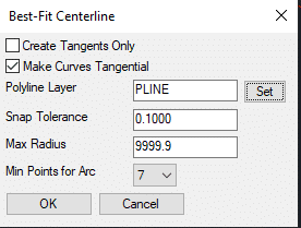
I often times will do this on the other side of the road as well. When this is necessary, you need to either make a new averaged centerline or create two different roads using one for each side. These cases are generally for older, small streets and roads where environmental conditions have caused heaving and erosion to move the curb. Logic says we will replace those sections so this is a rare exception, not the 
The new centerline is shown here. It deviates from the edge by almost 3-feet in the worst spot. This is too much. Changing the parameters will tighten things up. This is shown in the video.
With a good alignment to steer to, we will now work on the vertical.
Vertical Alignments
With horizontal alignments we are trying to get a centerline close to actual. With a vertical alignment, the stakes are higher. When the vertical profile corresponds with the centerline, it must follow road speed rules regarding cross-slope and the finished job needs to look good.
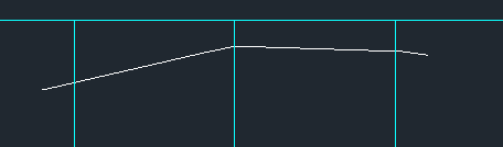
The job depicted above has 3D shots along the edge of pavement, as well as, centerline shots that are turned off. With these 3-points acting as cross-sections, we can create a good existing road surface as cross-sections. Don’t be alarmed if a contoured surface looks bad, a cross-section look is the best way to generate a finished product.
With the alignments done be assured you will be revisiting these to make things work better. We will generate cross-sections to verify the quality of the data.
The following is the Carlson section alignment dialog box. There are enough options to give you the results you are looking for. I am using these options for the job in this 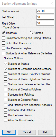
With the section interval and special stations defined, I will now create sections of the existing road to give me an idea of what I’m looking at.
Gathering Existing Data
I need to mention a critical point. When we work with clients who build models, we insist the shots are taken with a total station. GPS accuracy is not reliable for the number of required shots and would take too long to get low residuals. A robot and one person can shoot quickly and with accuracy to make sure we are not wasting time. We accept GPS shots only to fully rebuild the job after receiving good data.
Section Review
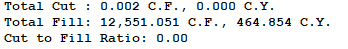
The production of cross-sections will be the true test of what needs to be done next. I have spent a lot of hours getting things ready for production on rehab jobs. The constraints of the existing features that remain and the rules imposed by the parameters of the road design make the task difficult. It may be necessary to rebuild the job several times in order to make everything work.
Also be aware of the hierarchy of importance in case something must give. For example, we need to keep the curb but need to go less than the required 2% slope. That’s an easy one, but there may be situations where several rules need to be flexed for things to work.
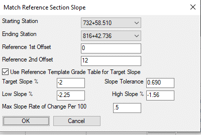
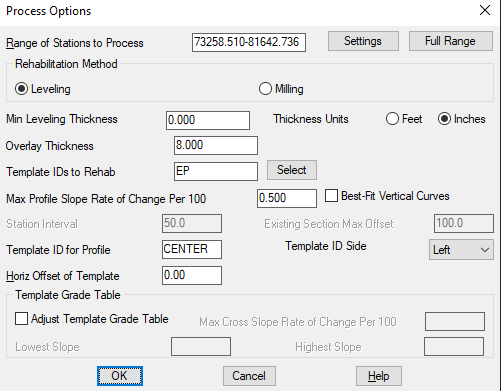
Carlson has a tool I have used with great success. The Match Reference 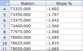
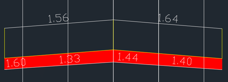
After filling out the dialog box, the command has listed the varying cross-slopes generated by the settings.
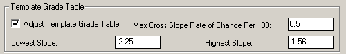
Adjusting the Parameters
Summary
The task may sound daunting, but the job needs to be broken down into the individual parts that make up the job. I have tried what seemed to be quicker and easier methods, but changes are near impossible and always take longer.
Approach each part of the process as a separate task and the delineation makes things easier to imagine. With more of these jobs coming along every day, it pays to be proficient.
I have featured Carlson because I have experience using the commands for road rehab projects. Other software can accomplish the same tasks. The commands will be different, but the procedure remains the same.