In construction, profit margins are measured in fractions of a percent, meaning a single grading error can wipe out weeks of earnings. Yet, many contractors make machine control modeling mistakes that increase their project costs unnecessarily. That’s why the difference between a profitable project and a financial drain is often your 3D data quality.
3 Critical Errors in GPS Modeling
Each machine control modeling mistake creates immediate consequences in the field, from equipment sitting idle to entire projects built in the wrong location.
1. Trusting Unverified Design Files
What works for design in an office doesn’t always translate to construction reality, which is why taking an engineer’s design file and sending it straight to the field without verifying it creates serious risk.
Common problems found in unverified files include:
Discrepancies between plan sets: Grading plans may conflict with utility layouts, creating impossible conditions in the field.
File incompatibility issues: Conversion between software platforms introduces errors that compound during construction.
Design omissions: Missing break lines, incorrect elevations or incomplete surface definitions lead to inaccurate models.
Outdated survey information: Base data that no longer matches current site conditions can create additional challenges.
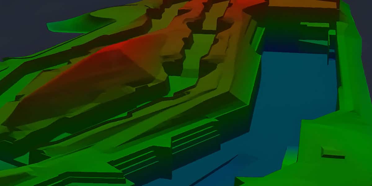
Site control establishes an accurate, localized positioning system on your construction site. This calibration step is the most important foundation for any GPS-guided project.
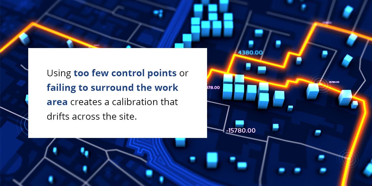
Improper site control causes the entire project to be built in the wrong place. Using too few control points or failing to surround the work area creates a calibration that drifts across the site. The result is millimeter-perfect grading in the wrong location, requiring complete rework.
3. Neglecting Operator and Field Crew Training
The most advanced machine control system is only as good as the person running it. This is why effective training that goes beyond software operation is vital.
Operators need to interpret the model, identify potential issues before they become problems, and communicate effectively with the office when the model doesn’t match field conditions. Without this training, crews end up troubleshooting basic issues that proper preparation would have prevented.
The Real Cost of Modeling Errors
These GPS modeling errors create financial and operational consequences, including:
Rework and schedule delays: A single construction modeling problem creates a domino effect. Correcting one error requires moving equipment, remobilizing crews, and redoing completed work. What starts as a minor modeling mistake can become days or weeks of delay that disrupts the entire project schedule and triggers penalty clauses.
Material wastage and budget overruns: Common machine control errors lead to over-excavation, excess material placement or incorrect grading that requires removal and replacement. The cost extends beyond wasted materials to include the fuel, labor, and disposal fees required to remove the unneeded material.
Safety risks and legal disputes: Hitting an unexpected utility line because of an inaccurate model creates serious safety hazards and project shutdowns.
How to Avoid Modeling Mistakes
Preventing these costly errors requires systematic processes and expert support. Contractors who implement these practices consistently deliver projects on time and on budget:
Establish a rigorous quality assurance process: Quality assurance for data preparation includes cross-referencing all plan sets, visually inspecting the 3D model for errors and verifying elevations against survey data. This process catches discrepancies before they reach the field.
Foster clear communication between office and field: Create a clear line of communication, so the team building the model understands field realities, and field crews know who to contact when the model doesn’t match conditions. This communication prevents small issues from becoming expensive problems.
Partner with a data preparation expert: Just as you hire specialists for surveying, structural engineering or other critical tasks, partnering with a dedicated data prep team ensures accuracy. Through their data preparation and modeling services, professional modeling teams can catch the errors that cause rework and protect your profitability.
Get Started With Take-off Professionals
Investing in professional data preparation protects your projects from costly errors. Specializing in 3D machine control modeling services, TOPS eliminates guesswork and prevents expensive mistakes. Our team of Data Engineers delivers precision models built specifically for machine control applications.
Contact us to learn more about how our data preparation services can safeguard your next project.
A grading crew completes a multi-acre commercial pad, only to discover the entire surface is 3 inches off grade. The design was correct, and the equipment ran consistently. But now you’re looking at full-site regrading, interrupted schedules and lower profit margins.
The problem isn’t always what you think. While accuracy and precision are used interchangeably as if they mean the same thing, they don’t. When your machine control model comes up short in both areas, it becomes an expensive rework. Knowing the difference between accuracy and precision is what separates a profitable job from a loss.
Defining Accuracy and Precision on the Jobsite
These terms measure two fundamentally different qualities in your site data and machine control systems. Confusing them costs you more than confusion — you’re looking at expensive errors you won’t catch until your equipment is already working in the field.
What Is Accuracy?
Accuracy measures how close your data comes to the true value. In earthwork terms, it’s about correctness. When your machine control model is accurate, the elevations and design surfaces in that model match the engineer’s specifications exactly. An accurate dozer grades to the true design elevation, not 2 inches high or 3 inches low.
What Is Precision?
Precision is all about repeatability. It’s the degree to which your system produces the same result under unchanged conditions. A precise machine control system delivers consistent measurements and equipment performance, pass after pass. Precision doesn’t guarantee correctness, only consistency.
The Target Practice Analogy
Picture accuracy and precision as arrows hitting a target. There are four scenarios that illustrate how these concepts work:
Low accuracy, low precision: Arrows scatter randomly across the target, missing the bullseye with no consistent pattern.
High accuracy, low precision: Arrows cluster loosely around the bullseye but spread out across the center zone.
Low accuracy, high precision: Arrows group tightly together but land far from the bullseye, consistently wrong.
High accuracy, high precision: Every arrow lands in a tight cluster at the bullseye center.
That fourth scenario is your goal. You need your data to hit the right target and hit it the same way every time.
Analyzing the Impact on Your Profitability
Getting these definitions right matters because each inaccuracy can affect your budget differently. When your model lacks accuracy, precision or both, the consequences show up as line items on your project financials.
The Financial Impact of Rework
Construction rework costs come from work that didn’t meet specifications the first time due to poor data accuracy or precision. You’re paying crews and equipment twice to complete work you already billed once. For example, on a $5 million project, even a 0.75% rework rate adds up to $37,500 in unplanned costs — money that comes straight out of your margin.
The Outcome of an Inaccurate but Precise Model
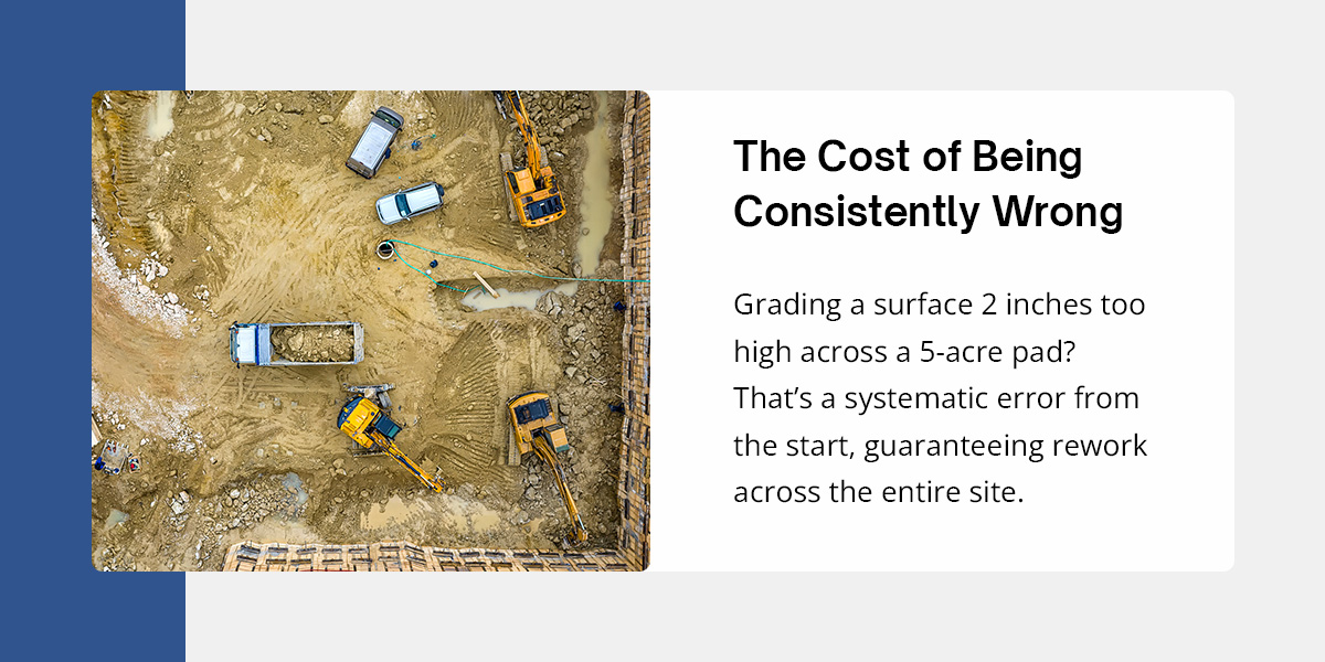
This is the “tight cluster, wrong location” scenario from the target practice analogy. Your machine control model is precise, guiding your dozer to perform the same action consistently across the entire site, but that consistent action is wrong.
Imagine grading a surface 2 inches too high across a 5-acre pad. The dozer delivers a level surface with minimal variation, but the elevation is off target, revealing an inaccuracy. This mistake has guaranteed rework across the entire site because the model had a systematic error baked in from the start.
Every pass your operator made was inaccurate. And often, you won’t catch the error until survey crews check grades, or you start the next phase, and nothing fits. By then, you’ve spent days of productivity on work that must be redone.
The Impact of an Accurate but Imprecise Model
Now, switch the scenario. Your model’s target elevations are correct, but the data itself is inconsistent. This situation happens when file conversions introduce errors, modeling workflows, cut corners, or quality control gets skipped. Your operator sees guidance that jumps around unpredictably from one blade position to another.
As a result, your crew might lose confidence in the system. Operators slow down, double-check everything manually, and essentially revert to traditional grade-checking methods. You’ve invested in machine control technology but haven’t seen the efficiency gains you expected. Projects take longer, and you’re paying for GPS accuracy you’re not actually using.
Achieve Precision to Build a Reliable 3D Model
Precision in your 3D model creates operational reliability that makes machine control versus traditional earthwork a legitimate productivity advantage instead of an expensive distraction. When your model contains inconsistent or noisy data, often the result of file conversion errors or flawed modeling processes,; operators can’t trust what they’re seeing on their screens.
A precise 3D machine control model provides consistent, trustworthy guidance that lets your equipment operator work at full speed. The blade or bucket moves smoothly from one elevation to the next without erratic jumps or conflicting data points. That consistency is what transforms digital models from design documents into field-ready construction tools that eliminate rework and keep projects on schedule.
Building on a Foundation of Confidence with Take-off Professionals
Accuracy gets your model to the right elevations. Precision keeps your equipment there, pass after pass. You need both, and there’s no room for compromise. Understanding the difference is important. Actually executing it requires specialized expertise, which most contractors handle through outside partners.
Take-off Professionals eliminates that gap. Our team of licensed, knowledgeable and experienced engineers and surveyors has spent over 20 years building verified machine control models. We deliver data that’s both accurate and precise, so your equipment does what it’s supposed to do the first time.
Commercial sitework leaves zero room for error. In an industry where profit margins are razor-thin, schedules are aggressive and labor shortages are a constant reality, a single utility strike or grading discrepancy can destroy a project’s profitability. For contractors, stakeholders, and owners, the days of relying solely on 2D paper plans or unverified CAD files are over. To stay competitive, modern projects require a “digital twin” — a precise, data-rich representation of the jobsite that ensures the work is done right the first time.
The disconnect between the design office and the field has historically been the primary cause of construction delays. Engineers design in perfect worlds, but contractors build in the real one. 3D Machine Control models act as the master blueprint that bridges this gap. By digitizing the project before a single bucket of dirt moves, these models provide a single source of alignment.
What Exactly Is a 3D Machine Control Model?
A 3D machine control model is a dynamic, engineering-grade representation of a site’s proposed topography and features. While 2D plans provide a flat view of “what” to build, a 3D model provides the “how,” adding the critical vertical dimension that defines slopes, drainage and elevation.
Take-off Professionals (TOPS) transforms static data, including CAD files, PDFs and survey points, into a living data ecosystem. This model becomes the “brain” for GPS-guided heavy machinery. When loaded into a dozer, grader or excavator, the model communicates directly with the machine’s hydraulics, automatically positioning the blade or bucket to match the design grade.
The Benefits of a High-Quality 3D Machine Control Model
Investing in professional data preparation is a critical form of project insurance rather than just an expense. A high-fidelity model transforms earthmoving and site utility management, delivering measurable returns on investment that often pay for the modeling service within the first week of operation.
Specific benefits include:
Significant rework reduction: 3D site modeling allows machine operators to hit grade with millimeter precision on the first pass. This enhancement eliminates the need for constant re-grading and minimizes the fuel, machine wear and labor costs associated with fixing errors.
Optimal material usage: On large commercial sites, an error of just a tenth of a foot across a parking lot can equate to hundreds of truckloads of material. A data-driven model facilitates precise volume calculations to prevent the common pitfalls of over-ordering expensive aggregate or underestimating export haul-off.
Increased on-site safety: By mapping underground hazards before excavation begins, crews can visualize and avoid high-risk assets like fiber-optic cables, high-pressure gas lines and electrical conduits.
Accelerated timelines: A machine control model feeds data directly into the cab, allowing equipment to run continuously without stopping for manual grade checks or surveyor staking.
Improved stakeholder communication: A clear 3D visual improves communication between technical field crews and non-technical government agencies or owners. It ensures everyone interprets the plans effectively, streamlining approvals and progress reporting.
Key Applications of 3D Machine Control Models for Commercial Sitework
Advanced modeling is increasingly essential for commercial developments of all sizes, from retail centers and office parks to industrial warehouses.
Pinpoint-Accurate Excavation and Grading
With a 3D machine control model, operators receive real-time cut and fill data on their in-cab displays. This feature allows them to grade complex slopes, retention ponds, and building pads within hundredths of a foot, drastically reducing the reliance on manual staking and survey crews.
Clash-Free Utility Installation
A robust 3D model maps out both existing and proposed utilities, including storm drains, sanitary sewers, and water lines. By coordinating with civil engineers during the modeling phase, TOPS identifies clashes digitally. Catching these conflicts before digging saves time and money for all stakeholders.
Verifiable Earthwork and Material Takeoffs
Winning a bid often comes down to who has the best numbers. Earthwork takeoffs generated from a 3D model provide the most accurate volumes for cut and fill, as well as site improvement material quantities. This precision allows contractors to bid competitively without padding their numbers for uncertainty. These models also provide stakeholders with verifiable data for progress billing. Instead of arguing over how much dirt the company moved this month, the data provides an objective record that speeds up payment applications and builds trust between the contractor and the owner.
Our Modeling Process: From Plans to Digital Site
TOPS functions as your external data department for engineering solutions. Our process catches errors early and delivers a product that is ready for the field immediately:
Data intake and review: We begin by analyzing your PDF plans and CAD files. Our team identifies missing data, bust points or design errors immediately. We often find that the grading plan doesn’t match the utility plan, structural details, or even the CAD drawings. TOPS can catch these discrepancies before you even mobilize equipment.
Model creation: Our specialists build 3D machine control models optimized for your specific fleet. We understand that a Trimble system reads data differently from a Topcon system. We are brand-neutral and ensure compatibility across all systems, so your mixed fleet works in harmony.
Quality assurance: This is the TOPS difference. A qualified Data Engineer reviews every node, breakline and contour. We check for tinning errors, where the software creates artificial triangles that distort the grade, and ensure smooth transitions. We also compare the model against the approved plans to ensure 100% accuracy.
Delivery: You receive a “plug-and-play” file ready to upload to your machines, along with a detailed report highlighting any discrepancies resolved during the process. We also provide ongoing support. If the plans change, we can rapidly update the model to keep your field crews working off the latest version.
Ready to Eliminate Surprises on Your Next Project?
In commercial construction, accurate data is the cheapest insurance policy you can buy. The cost of a model is a fraction of the cost of a single day of rework or a utility strike. Don’t let bad data or field guesswork eat into your margins. Ensure your next commercial sitework project runs on time and on budget by starting with a verified digital foundation.
Contact TOPS today for a free consultation on our 3D machine control modeling services. Upload your plans and let us show you how we can digitize your jobsite, streamline your operations and give you the competitive edge you need to win more work.
Modern farming requires calculated precision. Every acre has its own yield potential, but most farm operators can’t see what’s limiting those numbers until harvest comes up short. The difference between an average season and a record-breaking one often comes down to data you can’t see from the cab, such as micro-topography, drainage patterns and soil variance that can shift across a single field.
3D modeling for agriculture turns those invisible factors into actionable intelligence. These digital field maps reveal exactly where your land can support higher seeding rates and where you’re better off pulling back. Use them to transform precision planning from theory into measurable profit.
Turn Data Into Decisions
Traditional field knowledge shows you the surface. What it doesn’t reveal is the sub-inch elevation changes that send water pooling in one zone while leaving another bone-dry by mid-July. 3D modeling for agriculture serves as a mathematical digital twin of your land. It provides a precise grid that captures every slope, depression and drainage pathway across your operation.
A 3D model measures topography to fractions of an inch, creating a foundation for variable-rate decisions that treat each management zone according to its actual potential. It enables you to allocate expensive inputs only where they’ll generate returns, instead of wasting them in zones that can’t support the investment.
Get Higher Yields Through Precision Planting
3D models serve as the foundation for a prescription map. When the equipment enters a well-drained hilltop zone, the prescription automatically calls for increasing the seeding rate and planting slightly deeper to chase moisture. When it hits a low spot prone to spring flooding, the map signals a lighter population to avoid seed rot and preserve your investment.
The economic logic is clear. Precision agriculture technology enables you to achieve the maximum return to seed in each zone. A 3D model provides the spatial detail to fine-tune seed populations to the management zone level. Resource efficiency follows naturally. When you’re only applying premium seed genetics where they’ll thrive, you’re cutting waste in the zones that historically underperform.
Improve Water Management
Water moves across your land whether you manage it or not. The question is whether you’re controlling that movement or reacting to it after the damage is done. 3D farm planning models reveal flow patterns invisible to the naked eye. You can see where runoff concentrates, where drainage slows, and where erosion is carving away your most productive topsoil.
Drainage analysis: Software simulates rainfall events and tracks how water moves across the field surface, identifying natural channels and problem areas where ponding occurs. You can test different tile drainage layouts virtually before breaking ground, optimizing placement to handle both spring snowmelt and summer downpours.
Erosion control: The model pinpoints high-risk zones where slope and water flow combine to strip soil. Research on 3D buffer strip design shows that strategically placed vegetation barriers guided by elevation reduce sediment loss more effectively than generic edge-of-field buffers. Instead of guessing based on virtual estimates, a 3D model helps you target interventions where they’ll have the most impact.
Irrigation optimization: You can optimize irrigation by accounting for slope changes and soil variability. A center pivot sweeping across uneven terrain delivers inconsistent water application unless you adjust pressure and nozzle flow by zone. A 3D model allows you to design pivot systems that compensate for topography, ensuring even coverage and eliminating the dry corners that drag down average yields.
How to Build a 3D Field Model
Creating an accurate 3D field model is a multistep process that turns raw elevation data into a machine-ready asset your equipment can use:
The data from the equipment arrives as a point cloud with millions of unorganized coordinate points representing the field surface. It’s raw, noisy, and full of artifacts, such as equipment shadows, temporary debris and even the surveyor’s truck parked at the field edge. This area is where most DIY efforts stall out.
It’s also where 3D model data prep specialists step in. Take-off Professionals (TOPS) employs qualified data engineers who clean that noise, remove outliers and structure the chaotic point cloud into a usable surface model. They classify ground points separately from vegetation, correct for GPS drift and convert the data into file formats compatible with John Deere, Case IH, Trimble and other major precision agriculture technology platforms.
3. Deploy the Model to Your Equipment
Once you’ve processed the point cloud, you’ll have a final machine-ready digital elevation model that plugs directly into your tractor’s guidance system. Upload it once, and your equipment references it all season long. You can adjust planting depth, seed population and application rates in real time as you move across zones.
Take Your Farm’s Profitability to the Next Level
The bottom line is that 3D models pay for themselves by cutting input waste and unlocking yield potential in your highest-performing zones. Instead of adding costs, you’re reallocating resources to where they generate returns. Seed saved in wet depressions funds higher populations on prime ground, and fertilizer pulled back from thin hilltops gets redirected to deeper soils that can actually use it.
The best part is that you don’t need to become a data scientist to make this work. The complexity lives in the data prep, which encompasses cleaning point clouds, building surfaces, and formatting files for your equipment. That’s where specialists like TOPS handle the heavy lifting.
Our team processes about 1,000 machine control models per year across sectors, including the agricultural industry. We work with LiDAR models, aerial photogrammetry, and point cloud data from any collection method, transforming it into clean models compatible with all major equipment brands. You send us the raw survey files, and we return production-ready digital elevation models.
Are you ready to unlock the full potential of your fields? Learn more about the TOPS 3D modeling applications for modern agriculture systems. Contact our team today for additional information and a free quote.
Machine Control Modeling vs. Traditional Methods: What Contractors Need to Know in 2026
Traditional staking methods bleed profitability from every jobsite, from man-hours spent pounding wood stakes to expensive machinery idling while waiting for grade checkers. Manual layout methods simply cannot compete with the razor-thin margins and compressed deadlines defining 2026 civil construction.
Transitioning to machine control modeling is an important technology upgrade. It also represents a fundamental shift in how you can calculate profitability on the jobsite.
The Old Way: The Real Cost of Stakes and Stringlines
The physical limitations of a manual layout create a natural speed limit for your heavy equipment. A survey crew can only stake a finite number of points per day, and your high-capacity earthmoving machinery cannot move faster than the team on the ground. Every minute an excavator or dozer sits idle waiting for a grade check, money burns directly out of your project margin.
Relying on manual interpretation also introduces human error. Misreading a grade stake or incorrectly transferring data can lead to costly rework and significant material overruns. Traditional methods can also create safety risks as grade checkers work on foot in the blind spots of active heavy machinery.
The New Way: An Introduction to 3D Machine Control Modeling
Modern earthmoving relies on machine control modeling to create precise 3D digital models from construction plans. This process goes beyond standard GPS positioning by creating an accurate digital terrain model (DTM) or surface that interacts directly with the machine’s hydraulics to automatically drive the blade or bucket.
In this workflow, your operator views cut and fill data in real time on a cab display, eliminating the need to interpret external physical markers. The model translates complex engineering plans into a language the machine understands instantly. Most importantly, these models work across mixed fleets to unify your entire jobsite and ensure every operator works from the exact same dataset.
At a Glance: Machine Control vs. Traditional Methods
Machine control modeling provides many benefits over traditional methods.
Traditional Staking
Machine Control Modeling
Accuracy
Inconsistent
Precise
Speed
Slow
Fast
Labor Required
High
Low
Rework Risk
High
Minimal
Safety Risk
High
Low
Cost
Low
High
How Modeling Impacts Your Profitability
The shift to 3D modeling can deliver hard-dollar returns in three specific areas.
Faster Project Timelines
Machine control systems run continuously without stopping for manual grade checks, allowing your operators to maintain momentum throughout their shift. Additionally, work can continue in low-visibility conditions, dust or night operations, extending the billable hours in a day.
Significant Cost Reduction
In earthmoving, machine control increases efficiency by reducing errors. By achieving the correct grade on the first attempt, operators make fewer passes, resulting in reduced fuel consumption and less wear and tear on undercarriages.
Enhanced On-Site Safety
Machine control drastically reduces the need for surveyors and grade checkers to be physically present in the active work zone. When operators have full situational awareness inside the cab, they can focus on the environment rather than straining to read small numbers on a wooden stake.
Frequently Asked Questions (FAQs) About Machine Control Modeling
There are some key questions to consider before upgrading to 3D and GPS machine control modeling.
Is My Existing Equipment Compatible With Machine Control?
Most modern heavy equipment comes factory-ready for machine control. You can often retrofit older machines with aftermarket kits.
What’s the Real Return on Investment (ROI) of Switching to Machine Control Modeling?
While the initial setup has a cost, you may realize ROI within the first few phases of a single project through fuel and labor savings.
Who on My Team Can Use the 3D Model?
The model connects your entire field team. The operator uses it for guidance in the cab, the foreman uses it for progress tracking and volume verification and the surveyor uses it for quality assurance.
Making the Switch: Your Next Step Toward a More Profitable Jobsite
One of the biggest hurdles preventing contractors from switching is the fear of technical complexity, especially if you don’t have a tech team in-house. Outsourcing GPS machine control modeling removes that technical barrier, allowing you to leverage the full power of your equipment without adding overhead. Plus, the cost of not switching is the risk of being outbid by competitors who can move dirt faster, safer and cheaper than traditional methods allow.
Partnering with Take-off Professionals bridges this gap. We handle the complex data prep, ensuring your files are built for constructability, not just design.
Accuracy is the foundation of success, safety and profitability in any construction project. When minor layout discrepancies occur, they result in reworks, costly delays and budget overruns.
Historically, project layouts were established through manual staking, a labor-intensive process that relied on stakes, strings and human measurement. Today, the industry uses dynamic, real-time GPS-guided workflows to achieve precise construction layouts.
Understanding Real-Time GPS Integration in Construction
At its core, real-time GPS integration for construction involves a network of components that communicate to provide equipment operators with precise, real-time positioning data. This system consists of three main elements:
GPS rovers: A rover, mounted on a piece of equipment or carried by a grade checker or surveyor, receives satellite signals to determine its location.
Base station: An on-site base station receives the same satellite signals and, from its known, fixed position, calculates signal corrections. It transmits these corrections to the rover, refining its accuracy from meters to the subcentimeter level.
Software and 3D model: The software is the brain of the operation. It processes the corrected GPS data and continuously compares the equipment’s real-time position — such as the tip of a dozer blade or edge of a paver screed — against a preloaded 3D project model.
GPS and 3D Model Integration — From Design to Dirt
The true power of GPS staking lies in the seamless integration between digital design and physical work. The process begins in the office, where an expert creates a highly accurate 3D model of the finished site from project files or point cloud data captured by unmanned aerial vehicles (UAVs). This model is the single source of truth for the entire project.
Upon developing the digital blueprint, the professional then loads it into the equipment control systems in the field. The real-time data transfer between the office and the field enables operators to work from the most current plans. When the asset is active, the onboard system automatically guides the equipment or tells the operator precisely where to cut or fill to match the 3D model.
This construction GPS workflow eliminates guesswork and the potential for errors that arise from misinterpreting stakes or working from outdated plans. With improved accuracy, your project significantly reduces rework and helps you complete the project to specification the first time.
Using GPS Integration to Improve Layout Accuracy in Construction Applications
Improving construction layout accuracy occurs through specific, transformative changes to the workflows of heavy equipment. By replacing manual checks and visual estimation with continuous, model-based data, real-time GPS enhances precision in each phase of various applications.
Grading With Dozers and Motor Graders
In manual staking, accuracy is limited to the location of physical survey stakes. An operator must visually estimate the grade between the stakes, which can be dozens of feet apart, leading to inconsistent surfaces that require costly rework.
Real-time GPS in construction provides continuous, subcentimeter data on the blade’s position relative to the 3D model. It makes the entire surface a control point, eliminating the guesswork between stakes. The GPS automatically guides the blade to create a smooth plane or complex contour with an accuracy that manual staking and a visual operation cannot achieve.
Excavating With Excavators
With traditional methods, operators rely on batter boards, stringlines, grade checkers or surveyors inside the excavation, processes that are slow, less safe and prone to over- or under-digging.
In a construction GPS workflow, the system tracks the precise 3D position of the bucket’s teeth. The operator sees their bucket moving in real time against the 3D design of the trench or foundation on their in-cab screen. This view allows them to trace the exact lines, depths and slopes of the design, increasing accuracy and reducing risk, especially in hazardous locations.
Paving With Asphalt and Concrete Pavers
Pavers traditionally follow a physical stringline, which is challenging to set up and susceptible to bumping, sagging or other inaccuracies that are then permanently transferred to the paved surface.
The GPS creates a “virtual stringline” from the 3D model and automatically controls the paver’s steering and the screed’s elevation. This construction GPS workflow eliminates the potential errors associated with a physical line, resulting in a smoother, more accurate surface and precise control over material thickness, which directly improves quality and promotes efficient material use.
How Layout Accuracy Drives Project-Wide Gains
Achieving subcentimeter layout accuracy is a foundational benefit of real-time GPS construction, but its true value lies in the significant project-wide gains that this precision enables. By ensuring every equipment operates from a single, highly accurate source of truth, you experience improvements in speed, cost-control and adaptability.
Faster, More Efficient Layout Processes
Operators see their exact position relative to the final grade, allowing them to work continuously and bring surfaces to grade in fewer passes. This accurate, real-time feedback significantly accelerates project timelines and reduces fuel and labor costs.
Better Documentation and As-Built Verification
The GPS’s ability to accurately log the equipment’s position as it works creates a detailed digital map of the as-built conditions. This precise data provides an indisputable as-built survey that you can use to instantly verify quality against the design model, calculate material volumes for invoicing and streamline project handover.
Flexibility to Adapt to Design Changes
When you update a design, the new digital model is sent directly to the asset. The GPS’s inherent accuracy enables the operators to execute the new plan with the same level of precision. This agility eliminates the costly downtime and manual labor associated with restaking a site and completes a multiday process in a matter of hours.
Best Practices for Implementation
To successfully leverage real-time GPS in construction, you must focus on a disciplined, model-centric workflow:
Prepare accurate 3D models: The success of the entire system hinges on the precision of the initial 3D model. You must purpose-build this foundational element for equipment control.
Train crews on digital workflows: Effective implementation goes beyond teaching operators how to use the equipment. Crews must receive training on the complete digital workflow, from understanding the model to managing data in the field, to promote a smooth, efficient operation.
Manage data flow and version control: Implement processes to effectively manage data flow and control document versions. This improved construction GPS workflow enables everyone, from the project manager to the dozer operator, to work from the correct and most current model.
A New Standard in Construction Accuracy
Ultimately, using real-time GPS integration to improve layout accuracy in construction relies on a combination of advanced components, a disciplined digital workflow and practical equipment-level applications. From the initial site clearing to the final layer of asphalt, the result is a transformative gain in efficiency, quality and project-wide profitability.
Contact Take-off Professionals for GPS Equipment Control Modeling
The success of any GPS-guided project begins with a flawless 3D model, and partnering with a dedicated data preparation expert is the crucial first step.
At Take-off Professionals (TOPS), we offer comprehensive GPS and 3D equipment control modeling services to meet all your earthmoving needs. Our experienced in-house team creates purpose-driven, precise equipment control models from CAD files, paper plans or point cloud data, allowing you to build your project on a foundation of accuracy.
We provide 3D models compatible with all equipment manufacturers and support clients across all major U.S. time zones. With expertise dating back to 1988 and a track record of creating high-quality models, you can trust us as your ideal partner in all things data.
Drone technology and AI innovations continue to redefine how the world communicates, shares data and runs efficiently. Like all industries, construction is seeing the real-time benefits of an innovative 3D model and how it can reduce errors while improving efficiency. When integrating drone data into 3D construction modeling, the workflow advantages and depth of data available are hard to ignore.
The Value of Drone Surveys in Construction
Drone surveys are increasing in popularity across the construction industry, offering a faster, more accurate alternative to manual surveying. Their value in delivering effective, efficient project management is evident through:
Increased safety: Drones can conduct surveys and inspect sites from a distance without risking the safety of workers.
Project efficiency: Drone surveys quicken the construction process through innovations like Light Detection and Ranging (LiDAR) sensors. These sensors create intricate 3D maps of terrain.
Deeper accuracy: Construction industry professionals can use the high-resolution data collected from drone surveys for more accurate 3D construction modeling.
Reduced costs: Drone deployment can decrease labor costs. Additionally, drone data in construction can provide insights that cut project expenses.
Types of Data Collected by Drones
Construction drones gather various kinds of information:
Aerial Imagery
In aerial imaging, a combination of high-resolution cameras and photogrammetry processes images together into one output — a detailed, distortion-free 2D or 3D site model.
Drones collect aerial imagery and data in hard-to-reach areas, helping construction teams to find structural problems and deliver detailed reports to clients. These images are also vital for construction site planning, infrastructure layout and building information modeling (BIM).
Point Clouds
Point clouds are vast collections of data that represent a chosen geological area, structure or terrain. As a combined visual representation of a specific surveyed target, point clouds can enhance understanding while speeding up decision-making for clients and project managers. When critical information is required, this type of data collection provides a comprehensive look at realistic 3D models.
Topography
Topography studies the features of buildings and structures to provide surveys and data insights. Topography uses laser scanning to capture intricate 3D images with pinpoint accuracy. It provides a deeper understanding of how land and developments will coexist. Data collected from topographical surveys can also identify environmental factors to monitor erosion, ecosystems and uneven terrain.
Drone Mapping, Workflow and Actionable 3D Models
Effective drone mapping gives you the tools needed to create effective 3D construction modeling. Planning a successful drone survey includes considering how drone mapping and workflow steps can deliver the best results.
After the survey, these steps include:
Processing data: Using the gathered data to convert the photogrammetry and sensor information into actionable formats like point clouds, digital elevation models, and orthomosaics (geometrically accurate maps of overlapping aerial imagery).
Importing and integrating data: Exporting this processed data to be used in CAD or BIM software to create detailed and accurate models that can be integrated with project management platforms.
While no two drone mapping workflow plans will be the same, having these steps in place streamlines the process of getting information, understanding unanticipated problems and delivering actionable data that can accelerate project schedules.
Machine Control Modeling and Site Planning
Construction site planning that incorporates 3D machine control modeling guides earthmoving machinery and grading equipment via digitally enhanced blueprints. Real-time drone data helps machine operators ensure accurate alignment, depth and slope.
As sensors and other innovations continue tracking the machinery, the chances of error or unexpected safety issues decrease, while the drone data construction model can provide progress and analysis. This can also apply to quick volume calculations during excavations to maintain cost management information.
These benefits also help streamline communications between field and office teams and foster a deeper understanding of expectations and next steps.
Best Practices and Considerations
3D construction modeling provides many benefits. To fully make use of it, you’ll want to take some considerations to take into account. For effective drone mapping, workflow and 3D modeling, make sure:
You choose the right hardware and software to get the best data out of your drone surveys and findings.
Your construction team and all other necessary staff are trained fully in how to best use these technologies.
You have processes in place to ensure collected data is actionable, accurate and consistent.
Your drone mapping and workflow are integrated as one cohesive process.
Keeping these best practices in mind will help you maximize the use of drone data.
3D Models and the Importance of Data
Safety, efficiency and accuracy are essential parts of any successful construction project. Collecting data and implementing it effectively reduces safety hazards, costs and the potential margin of error. Using drone surveys and 3D models gives you the best possible data so you can use the most effective information in your workflows.
Take-off Professionals prepares 3D models for site work, machine control and layout. With over 20 years of industry experience and a close to 1,000 machine control models created yearly, we place actionable project data directly into our clients’ hands, giving them the confidence they need for a successful bid and project completion.
We work on projects of all sizes and scopes. Contact us to learn more.