
Let’s get to the meat of the program and see how data is produced. Before sending things out to the field, we need to make 2D and 3D lines as well as points. As I go through the steps, you will see some different approaches to the process that may help users with various situations.
JUMP TO SECTION
Getting Around
You will need to get some things out of the way to create data. Starting with Drawing Cleanup is where we’ll begin. There are a lot of options for cleaning including bringing in CAD elements that may otherwise get lost in other platforms.

The following settings will work fine for this drawing. When completed I can get the layers stripped and create a layer state for building data.
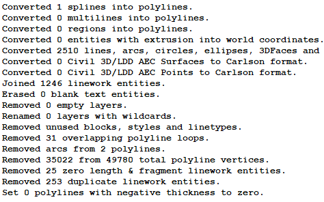
Listed below are notes on Drawing Cleanup results:
• I got a lot of help here with lines and verticies. I will add line points back later, but at this stage I want a straight line to have no interruptions until I add them.
• The duplicate lines were extreme in this file. Looks like it came from a couple xref plan lines that were stacked on each other when they exported everything to one file.
• The conversion of different linetypes into polylines will make things easier. Sometimes when you are elevating along curb, the line will break because it is next to a different type. Now I can join and elevate easier. This process is critical not only for data, but the field controllers will either not display or even crash with other than polyline exports.
With the unnecessary layers turned off, we are now ready to produce a file to send to the field.
The Commands
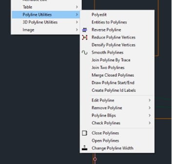
• It is easy to convert any line type to a polyline.
• Direction can be reversed to help joining lines.
• Individual lines or layers can reduce or densify vertices.
• Points at intersections can be added.
• Move the start of a line.
• Add or remove arcs from polylines. An arc cannot be elevated so segments must be added for elevations to be added.
• Highlight non-tangent, non-perpendicular, crossing, and unclosed polylines. These tools are great for getting to the bottom of problems with detail areas in a model.
Elevating polylines can be done with the command shown. The properties can be changed as well so you know what has been elevated.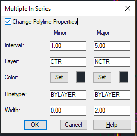
• Lines can be re-layered if desired.
• Color can be changed.
• Line type and the width of the lines can be changed.
A tip I like to use is to re-layer the location of the elevated polylines and make that layer un-selectable in case you pick the line again so it does not get changed. While in the process of making contours, it is a good time to check and see if there are any additional line fragments under or maybe copied to the new layer. Housekeeping at this point is critical.
3D Lines
Elevating curb lines is the most tedious and potentially problematic part of civil site data. We can go through the plans and pay attention to called out elevations to correctly enter them into the right vertex. Only after the model is built and the line is offset for back of curb do we sometimes notice an issue.
Carlson has helped with a visual representation of a polyline as you add elevations to spot issues before going too far.
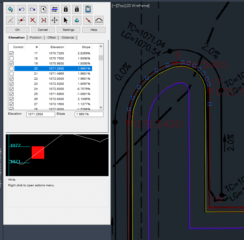
In this image we see the polyline edit functions. I will outline this in the video but it is worth drilling down here.
• The profile box shows the elevation of the selected node.
• If I add a checkbox, it will hold that elevation.
• Incoming and outgoing slopes are shown.
• I can add vertices by double clicking anywhere on the line.
• I can move a vertex to adjust line location.
• Vertices can be added by crossing polylines, useful for elevation callouts that have a leader intercepting the subject line.
• If I have a surface, any location on the line can be elevated by the surface.
The process of going through a line and elevating can go quickly. Using the profile will expose fat-fingerings as well as incorrect callouts.
Curb Offsets
I use the Offset 3D Polyline command for curbs. I will discuss that in a moment but wanted to go over the dialog box because it contains a lot of information.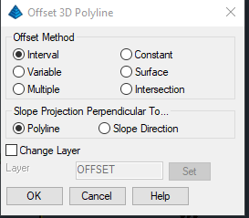
• The Variable method allows you to change the settings per line.
• We will cover the Multiple method in more detail later.
• Constant method will perform a horizontal offset and make the line into a single elevation. Think building pad offset or basement excavation.
• Surface method lets you make a defined slope into an existing surface for a daylight line.
• Intersection method is for making a 3D line at the potential intersection of various slopes and two reference polylines.
• The layer of the newly generated line can be placed on a new layer.
The Multiple command is a strong tool. Here are some details.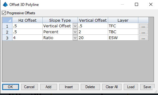
• There are three slope options available. They are Vertical offset (in feet), Percent (can be positive or negative), and Ratio as the entered number x:1
• While in the command I can make a layer name without going back to the layer manager. The layer color will be white with a solid line but that is easy to change.
• A click on the three dots that are to the far right, will bring up a layer list where I can pick the correct previously entered layer. Any difference to an existing layer entry from spelling or spacing will create a new layer.
With CAD standards it is easy to pick the layer name from the dropdown menu when things are set up well. Always bring a drawing into your established template.
Improving a surface
When the basics are out of the way, you will need to clean up areas that are not performing well. Adding breaklines in Carlson is not as easy as other programs mainly because the surface needs to be remade to see the changes. Not a big deal but real time work is not possible. In this case, I would use tight tolerance contour lines (.1 feet) to see results in plan view before going to 3D view for confirmation.
The process is not difficult, and it is made easier when using SiteNet because layers do not need to be turned off for the surface to be made. I’ll go over this in the video.
When adding additional 3D information to a job there is a slippery slope. Less is more but how do you know? Here are some guidelines.
• First make certain that you need to add not take away. In other words, can you trim a line a bit or delete something for the surface to perform better?
• Always put breaklines on their own layer. Sometimes I won’t include the breaklines in a surface to see if I did too much.
• This is the most time intensive part of a project. To become proficient practice on small sites. Large jobs can have hundreds of “improvements” and many of which are not needed.
Making Surfaces
It is easy to make a surface for a software’s field computers. Carlson has field software but what happens when we build for another brand? We have the best luck with xml surfaces and either dwg or dxf for linework.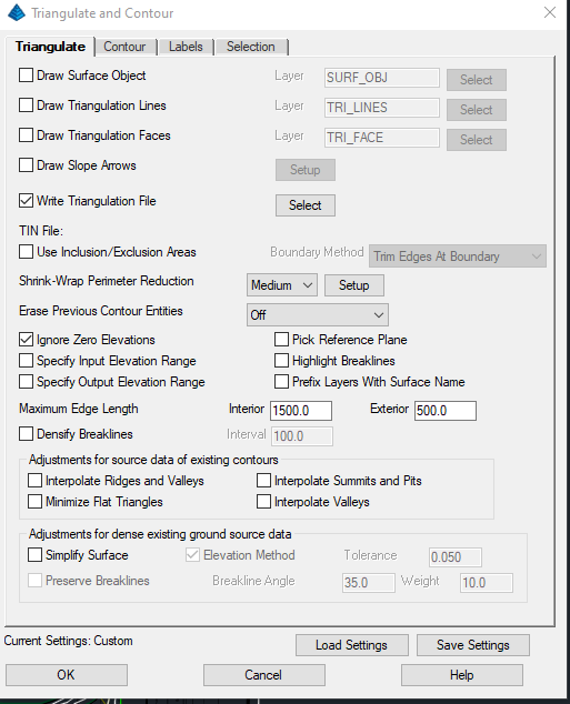
• The tabs let you control contours and labeling. You are also able to choose the data types to be used for that surface.
• TIN lines and/or faces can be drawn.
• Slope labels can be added to the screen.
• Boundaries can be drawn in CAD and selected. Carlson can also shrink wrap the surface elements.
• You can model a cliff by changing the reference plane.
• There are some great tools for existing surface production. These tools are useful when you have a big group of contours.
Exporting Data
The following outline is our practice for exporting surfaces.
• We make Carlson TIN files. It is native to the program and is needed for many of the tools.
• We verify the linework is polylines and joined where needed. This is for 2D lines only and that work was done for converting things to 3D, so they do not need to be reviewed.
• We will use a dwg export if the field software is able to convert it, dxf is the second choice and is usually a larger file.
• Xml export is easy to work with, just be sure you have the correct units.