
The processes involved with building roads, railways and canals often involve adding or removing large masses of dirt and stone. This addition and removal of mass is called cut and fill in the excavation industry. Cut and fill is a common process where the movement of the earth is handled in a logical manner.
The goal of cut and fill is ultimately to conserve energy and maximize the use of existing materials to avoid bringing in or shipping out dirt mass. While common, it can be an exhaustive process — moving earth takes a great deal of labor, and mistakes can lead to costly rework. To avoid such problems, project planners use detailed and intelligent cut and fill maps, providing exhaustive plans to help guide excavation teams to the most efficient use of mass and labor.
Maximize Your Cut and Fill Projects With Us!
Planning critical cut and fill projects? Let Take-off Professionals guide the way! Our diverse data services and 3D models can transform your terrain data into meaningful insights for optimal terrain utilization. Whether you employ Carlson, Leica, Topcon, Trimble, Civil 3D, MicroStation or any design software, our expertise can cater to your needs efficiently.
JUMP TO SECTION
What Is Cut and Fill?
So what exactly does cut to fill mean? Cut and fill excavation, also known as excavation and embankment, involves removing (cutting) soil from higher areas and using it to fill lower areas, creating a level surface. This process balances earth movement, reduces the need for imported material, and is essential for preparing sites for construction.
The two terms are defined as follows:
- Cut: Earth that is removed from an area is considered “cut” or excavated earth.
- Fill: Earth that is brought into an area is considered “fill” or embankment earth.
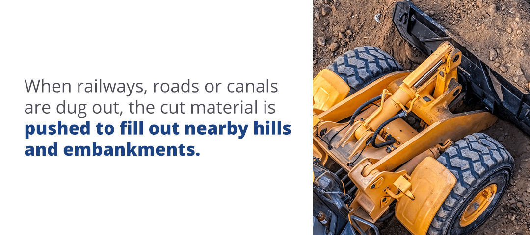
When railways, roads or canals are dug out, the cut material is pushed to fill out nearby hills and embankments. This process is usually accomplished with earthmoving equipment. Bulldozers and excavators remove land from cut locations and transfer it to dump trucks, which carry it to fill locations. Once the land is transferred to the fill location, the filled earth is compacted with a roll-style or plate compactor.
This compacting process removes air before any construction takes place. It’s essential, as it prevents the earth from moving and settling during or after the construction process, which can damage the foundation and building features.
In cut and fill excavation, the ultimate goal is to conserve mass as much as possible. Having more cut than fill results in project managers needing to find somewhere to dump excess rock and soil, while having more fill than cut results in the manager needing to bring in dirt from another location. Both of these outcomes result in extra material, labor and equipment costs. To avoid bringing in or removing excess mass, cut and fill processes are planned in a way to keep cut mass and fill mass approximately the same.
While effective at conserving mass, cut and fill is an expensive process. The cost of this kind of excavation increases as more land is moved and more equipment and labor are needed to do so. To help maximize the use of earth, equipment and labor, site planners often use what is called a cut and fill map.
How Are Cut and Fill Maps Used?
When they’re planning areas where cut and fill is required, designers create drawings called cut and fill diagrams. These diagrams illustrate all the areas where cut or fill are required. Such maps are generated by taking highly precise measurements of the existing topography and elevation, then overlaying a map of the desired topography. In these maps, cut and fill are defined as follows:
- Cut: Areas where the existing elevation exceeds the desired elevation have the “cut” material.
- Fill: Areas where the existing topography lies below the desired elevation line are the “fill” spaces.
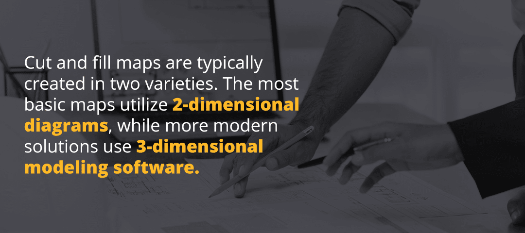
Cut and fill maps are typically created in two varieties. The most basic maps utilize 2-dimensional diagrams, while more modern solutions use 3-dimensional modeling software. These two options are explained in more detail below:
- 2-dimensional diagrams: At their most basic, cut and fill diagrams show a location along an X-axis with a positive or negative Y-axis, quantifying the amount of cut or fill with a negative or positive number, respectively. Since land exists in three dimensions, these diagrams must be created for multiple cross-sections of the landscape at regular intervals.
- 3-dimensional diagrams: 3-dimensional maps are more modern solutions for cut and fill excavation projects. The terrain is first measured using accurate surveying equipment, and the data points are used to create a software-generated model of the terrain. Once the base model is complete, the planner creates a model of the desired terrain and lays it over the existing terrain model to identify the cut and fill areas in three dimensions. Software models may highlight cut vs. fill areas with different colors that vary based on value ranges.
Choosing to use a 2-dimensional model over a 3-dimensional one should depend on the level of accuracy required for the project. Smaller-scale projects with limited cut and fill needs may not require more than 2-dimensional diagrams. Larger and more expensive projects, however, will usually require the accuracy provided by a 3-dimensional diagram. Beyond this difference, the ability to use one type of diagram over another depends on access to the site and equipment availability.
Terrain Features in Cut and Fill Maps
Cut and fill maps contain many of the same terrain features as traditional maps, though they often also include elevations for the purpose of calculation. Some of the common terrain features included in cut and fill maps are detailed below:
- Hill: A hill is defined as an area of elevated ground where the ground rises at a slope. Hills are shown on maps using contour lines that form concentric circles. The closed circle that’s smallest represents the hilltop.
- Saddle: A saddle is a low point between two points of high ground. It may appear as low ground between two hills or a break or dip along a ridge crest. This feature is typically represented on the map with an hourglass shape.
- Valley: A valley appears as a long groove in the land and usually contains a stream or river flowing through it. On a map, valleys are usually represented by contour lines in a U or V shape with the closed end pointing upstream. Draws are less prominent versions of valleys and are notated in the same way.
- Ridge: A ridge is an area with steep slope and high ground on one side. Usually, ridges will be shown with contour lines forming in a U or V shape with the closed end pointing away from the higher ground. Sometimes, spurs form from ridges, appearing as continuous lines of higher ground jutting out from the ridge. They’re noted similarly, though they may affect the shape of the ridge.
- Depression: Depressions are low points or sinkholes in the ground. Maps usually show depressions only if they are significant enough in size, and these features are notated by closed contour lines with tick marks pointing to lower areas.
- Cliff: A cliff is a sudden drop-off, appearing as a vertical or near-vertical change in elevation. Cliffs usually appear as contour lines being drawn extremely close together or on top of one another.
From the complete map, cut and fill can be planned around existing topographical features. Commonly, a map with these features may be used as a base, with the final project laid over it to determine areas of potential cut and fill. Once initial plans are made, cut and fill plans are added based on the topographical features.
How to Calculate Cut and Fill
So you’ve determined that you’ll need to use cut and fill excavation in your project, and you have an idea of what method you’ll be using. How do you calculate cut and fill area so that you can plan out the labor and calculate your project costs? The calculation method depends largely on the method you’ll be using in your project.
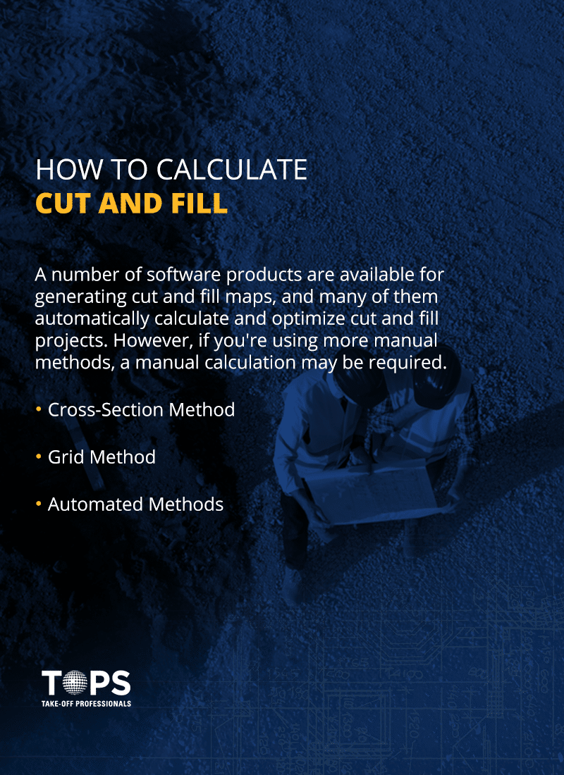
A number of software products are available for generating cut and fill maps, and many of them automatically calculate and optimize cut and fill projects. However, if you’re using more manual methods, a manual calculation may be required. A variety of calculation methods are used to calculate cut and fill values, and some of these methods are detailed below.
1. Cross-Section Method
The cross-section method of calculation is a common method used with the 2-dimensional method of mapping. With this method, cross-sections of the existing and proposed land levels are measured at regular intervals across the site. The cut and fill area is determined for each cross-section, then adjacent cross-sections are compared and the averages of their cut and fill areas are multiplied by the distance between them. This is done for each adjacent pair of sections, then the total volumes are added together to create the complete cut and fill volumes for the project.
The cross-section method of calculation is considerably more time-consuming than automatic methods of calculating volume, and the accuracy of the method depends on the distance set between sections. Closer sections result in greater accuracy but take longer to calculate, while further sections are less accurate but take less time to calculate.
2. Grid Method
The grid method of calculation involves drawing a grid onto the plan for the earthwork project. For each node of the grid, determine the existing and proposed ground level and calculate the cut or fill required. Once the cut or fill depth is calculated, multiply the value by the area of the grid cell. Do this for each square of the grid, then add the volumes together to determine the total cut and fill volumes for the project.
Like the cross-section method of calculation, the grid method takes time to implement and is significantly more time-consuming than any automatic systems. Additionally, the accuracy of the grid method depends on the size of the grid cell. Larger cells take less time to calculate but are less accurate, while smaller cells are more accurate but take more time to calculate.
3. Automated Methods
If you’re using an earthwork software, you may not need to use one of the manual methods above. Instead, the software will run the calculations for you. It should be noted that these software systems are faster but not inherently more accurate — for example, some software calculations are based on high-density versions of the cross-section or grid methods. However, automated systems often use more sophisticated calculation methods, such as the triangular prism method.
The triangular prism method is a common calculation method for earthworks, and it’s favored for its excellent accuracy. However, it must be completed using software due to its technical complexity.
The triangular prism method starts by triangulating the existing terrain to create a continuous surface of connected triangles. The same method is used to model the desired terrain. Once both surfaces are complete, the triangulations are merged to create a third triangulation. Once merged, the cut and fill is calculated by taking the volumes of the generated triangles and adding them together. Because of the excellent representation of both the existing and desired terrains, this method presents an excellent representation of volumes for cut and fill projects.
Technologies and Tools for Cut and Fill Mapping
When you prioritize energy conservation and resource maximization, it’s essential to use the most efficient cut and fill mapping technologies and tools. Having the right resources will enable you to accurately map your worksite and enhance your control over project results.
Various modern technologies and software applications, including 3D modeling, drone surveys and GPS or GNSS systems, generate accurate cut and fill maps quickly and efficiently. They offer the real-time data you need to make informed decisions about resource allocation, cost estimates and other project details.
3D Modeling
3D models create a detailed, easy-to-understand cut and fill map of your worksite. With realistic models of your project, you can easily and accurately complete the necessary calculations to ensure resource optimization and efficiency.
Benefits of 3D modeling include:
- Accuracy: Using 3D models for cut and fill maps gives you a scaled replica of your worksite. You can take precise measurements of stockpiles, slopes and other essential project features to create accurate cost estimates and improve operational efficiency.
- Cost savings: With 3D modeling generating your cut and fill maps, you can move earth logically and accurately according to your job site capabilities and available resources. 3D models can help reduce labor, equipment and material costs by ensuring your resources are always used effectively.
- Communication: A 3D model offers a real-world visual of your worksite, providing a clear understanding of the project’s scope for engineers and clients. With a clear image right in front of you, you can communicate needs and optimize resource allocation more easily.
Related Article: The Ultimate Guide to 3D Modeling in Construction
Drone Surveys
Drones fly at a low altitude to produce high-resolution images of existing elevation and topography. The detailed pictures they capture allow you to take accurate measurements for precise cut and fill mapping.
Using drone surveys for cut and fill maps offer several benefits, including:
- Increased safety: Drones can access hard-to-reach and even dangerous areas, increasing the safety and efficiency of your workforce.
- Continued operations: Since drones fly above your worksite, they will stay out of operations and away from resources so your work can continue on schedule.
- Improved reliability: You can quickly and accurately gather data, map topography and measure stockpiles with a drone since they can provide visuals of multiple angles.
- Saved time: Drones work faster than many other manual cut and fill mapping methods, especially since they enable you to take measurements and map out cut and fill operations from a single location while they fly over the area.
- Decreased spending: With less downtime, better affordability and faster processes, drones can help you save costs on cut and fill mapping.
GPS/GNSS Systems
Global positioning systems (GPS) and global navigation satellite systems (GNSS) are valuable tools that streamline cut and fill mapping processes. Using GPS or GNSS on your worksite will enable you to:
- Make informed decisions: GPS and GNSS offer accurate, real-time data, helping you make informed decisions that improve efficiency. You can experience greater precision in cut and fill mapping, cost estimations, projected deadlines and other essential worksite needs.
- Save time and money: Advanced tools like GPS or GNSS allow you to make accurate calculations quickly and easily to save time and effort. Automation will help you save on labor and energy costs.
- Improve safety: These tools offer increased safety since you can operate them from a distance with high levels of accuracy and reliability. This flexibility helps to protect your workforce while maintaining precision and efficiency.
- Enhance efficiency: Since GPS and GNSS provide greater accuracy than some manual measurement methods, you’ll experience fewer errors that would otherwise increase costs and waste time. These tools can help optimize processes for improved productivity.
3 Common Challenges and Solutions for Cut and Fill Mapping
Exact cut and fill calculations are vital throughout every project stage. It is essential to address mapping challenges such as data accuracy, varying site conditions and slope stability to ensure your project moves forward on time and within budget. With proper surveying techniques, data validation methods and risk management practices, you can mitigate cut and fill mapping challenges and streamline projects.
1. Data Accuracy
Precise cut and fill excavation efforts will save time, reduce labor costs and improve operational efficiency, but creating the precision that cut and fill mapping requires can be challenging. Cut and fill processes rely on accurate information about topography, stockpiles and other worksite details to ensure resource optimization and seamless project progression.
Data accuracy starts with how you collect data. Modern cut and fill mapping technologies and software enable you to gather correct data from the project’s start. If you start your project with quality data, you will be better equipped to create quality results.
You can also improve data accuracy through data validation methods. When you verify the data gathered from mapping technologies and software, you can ensure information is correct and aligns with project specifications.
2. Varying Site Conditions
Worksites often have varying site conditions, especially when your project covers an extensive area. Multiple terrains, slopes and soil qualities can add complexities to cut and fill mapping and operations. Accurately mapping your worksite is essential to project success, especially when managing multiple variables.
Even if your site is relatively small or the terrain is consistent across the area, you may experience changing site conditions over time. Your worksite is susceptible to weather, erosion and other natural and uncontrollable factors, leading to varying conditions throughout the project’s duration. These variations are important to monitor and manage to ensure worksite safety and stability.
Beginning your project with proper surveying techniques will enable you to mitigate the challenges of changing site conditions. Continuing to monitor your site with the right tools and technology can also help you manage site conditions by:
- Creating accurate cut and fill maps: Modern technology will precisely calculate, measure and generate cut and fill maps that account for varying site conditions.
- Boosting efficiency: You can streamline operations with the right tools and technology, driving your productivity.
- Saving time and costs: Using advanced tools and proper surveying techniques can save you significant time, energy and costs throughout your project.
3. Slope Stability
A stable slope can support its own weight and other external forces without soil or rock displacement. Creating this stability is essential in cut and fill operations. Aerated soil or miscalculated cut and fill slopes can lead to significant issues later in the project.
Balanced, stable and safe cut and fill slopes can be accomplished with accurate data collection and mapping. Modern tools and technology can bring the precision your worksite needs to mitigate slope stability challenges and ensure safety and efficiency.
You can also manage slope stability risks using risk management practices that improve cut and fill mapping and ensure accuracy. Consider implementing procedures such as:
- Identifying risks: Brainstorm what risks your workforce could encounter when mapping cut and fill construction, collecting data, reviewing slopes, performing calculations and working safely on the site.
- Assessing potential impact: Rank risks based on their impact on budgets, deadlines, slope stability and worksite safety to determine which risks require priority attention.
- Preparing a response: Decide how you will mitigate each risk, such as using 3D modeling to ensure accurate calculations for mapping or drone surveying to keep your workforce safe when gathering data.
- Monitoring conditions: Consistently track and evaluate project progress, especially during cut and fill operations, to ensure your workforce follows risk management practices.
Work With the Data Preparation Experts
The cut and fill process is an extremely useful process for excavation in residential, commercial and roadwork projects. However, while cut and fill makes use of existing terrain, it requires detailed planning to be as effective as possible. To accomplish this goal, project planners need detailed cut and fill maps — that means they need survey equipment to get terrain information and software to process and visualize data in a meaningful way. Take-off Professionals can help.
Take-off Professionals prepares 3D models and performs related services for a wide variety of industries, from commercial construction to civil engineering projects. Our innovative data services are available to help take your terrain data and turn it into meaningful models that you can use for your next cut and fill project.
TOPS works with a wide range of systems, so we can provide services to as many companies as possible. We work with data from Carlson, Leica, Topcon and Trimble equipment and can provide models in any format you need, whether your engineers use Civil 3D, MicroStation or another design software. We can even work with multi-brand fleets.

When you work with us, you can trust our decades of knowledge and experience as well as our innovative GPS and 3D machine control services technology. With our tools and services, your business can gain detailed insights into your project to help make the most of your cut and fill terrain.
Want to learn more about our models and how they can help on your next cut and fill project? You can get in touch with our team of data preparation experts right away by completing our online contact form or calling us at 623-323-8441.