There is nothing more difficult, or rewarding, than seeing a highway job perform well from dirt work to paving. It takes years of experience to fully understand the process. My advice is to think differently about the approach. In upcoming blog posts, I will go over the different approaches available for both Trimble Business Center and Carlson. These will be high level overviews of the enhancements we use for basic road elements. If you are a beginner, we will offer resources to get you up to speed.
JUMP TO SECTION
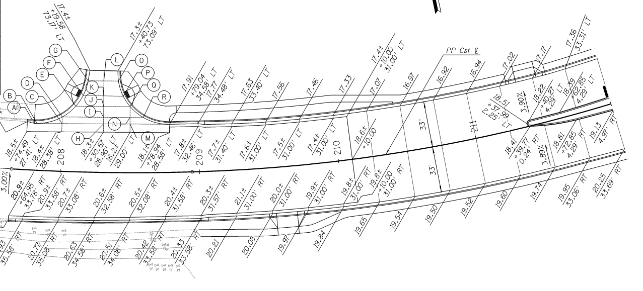
Horizontal Alignment
The coordinate geometry (COGO) of a road, or construction centerline, can either be a quick data entry job or an enduring nightmare. 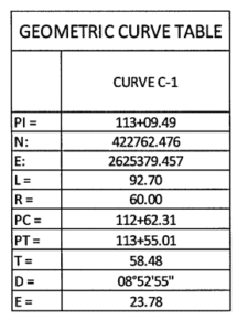
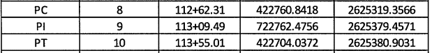
- Enter the PC, PI, and PT coordinates and stations first. Then enter per the plan.
- Adding the delta and the curve will help resolve calculation issues.
- Recheck the other numbers to see how close you are to discover errors.
- You may not need to contact the engineer if the numbers are close. However, close is relative and a lot of bad curves can affect the length of a centerline.
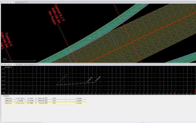
- When the centerline is a median, or other non-road geometry, offsets will need to guide the actual construction. Be certain the horizontal and vertical alignments are correctly matched in all three dimensions.
- Not all field software can handle Station Equations. The rover can decipher the information while the machine cannot. The short answer is to make two files and overlap the data a few hundred feet so the operator can make fewer file changes.
Vertical Alignment
Vertical alignments are generally not as challenging as horizontal alignments. The most common issue is reworking an asymmetrical vertical curve. I’ve listed some tips below:
- A road starting mid-vertical curve with no information for the PVC can either be scaled or some math should be performed to get the curve right.
- Rehab profiles sometimes come without instructions for the new alignment. Rules need to be applied to the existing profile to identify the adjustments. The reason is when there is a mill and fill requirement, a survey crew will stake and set up the road. This should be done electronically. It takes more work since the alignment needs to be drawn or imported from a profile view in CAD. (I will describe this process in more detail in a future article.)
- When encountering bridges, it may be tempting to ignore the vertical curves to save time. Always include them to troubleshoot design issues during construction.
- The vertical is not always in the center of the road. Worse yet, it can shift during the job. Don’t be concerned about stopping and starting a road job at a station where this occurs.
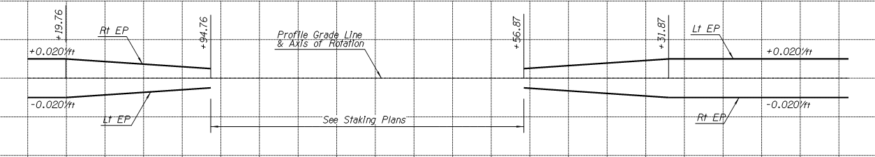
Super Elevated Curves
Super Elevated Curves are not hard to understand. Where they are challenging is getting the standard details to match the cross sections and super diagrams. The transitions can also cause confusion. There are conflicting opinions on guidelines to use for Super Elevated Curves dependent on the state or country we are working in. The following are the general guidelines that we use.
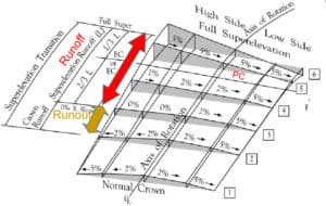
- Normal Crown
- Runout is the length of roadway needed to accomplish a change in the outside lane cross slope from normal rate to zero.
- Runoff is the length of roadway needed to accomplish a change in the outside lane cross slope from zero to a high side crown slope (usually 2%). Some explanations stop there and use this term to detail the rest of the transition.
- Runup is the length of roadway needed to go from a straight cross slope percentage to full super.

- A lot of state formulas are produced by transitioning some fraction of the curve length, usually by thirds. This diagram displays basic rules that many DOTs follow.
- Note the axis of rotation, it can change and shift when super curves are drawn by engineers using older software. Also be aware of an old job that’s received funding and plans have not been updated.
Templates
Now that we have a good foundation for making a corridor, it’s time to attach templates to the alignments. I build roads planimetrically with as many pieces and parts required to get it right. Planimetric roads are a combination of templates and plan based features.
- Driving lanes always require templates; at least in areas without intersections.
- Intersections will require more data.
- Drainage elements, like ditches and culverts, are sometimes only available in plan view. They generally take a lot of time to calculate and make into a template element. Best to drop them on the screen.
- The further you go outside the roadway, the less you need that data on the road file. Consider putting retentions and other out of bounds work into a separate grading file.
Details
The basics are done. We have a road on the screen. It is critical to remember that we are only building part of the information on the plans. Any questions can be answered in the standard details provided by the agency. 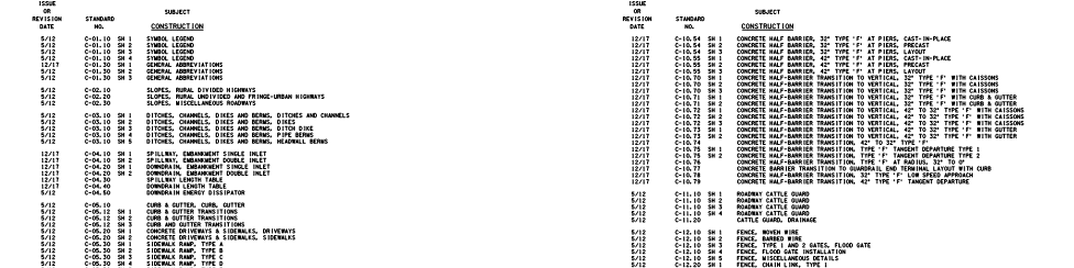
Rideability
A lot of money is earned by meeting specs for a rideability bonus. All roading software has a way to check for the IRI, (International Roughness Index). This checks the current profile as drawn in the plans. We will often see a profile that is very close to the desired index. In other words, if the road exceeds the drawn profile by a small percentage, the index will not be met. In that case we will recommend a value engineering profile adjustment that will give the contractor a better chance of getting the bonus without affecting the road. Designers will often get a profile drawn by software, the algorithms do not take rideability into account; we are just offering the owner a chance to get a smoother ride for the user. Contractors will often get automated paving equipment paid for in a bonus depending on the size of the job. This reinforces my advice to be sure the driving lanes are produced with templates. Everything from widening to supers are better generated with templates for the software to correctly transition these and other elements.
Software
New hardware used in the field has capabilities that can benefit from the enhanced data from software. Terramodel and other previous generation tools did an adequate job but the data was not robust enough to effectively drive modern grading and paving equipment. Make sure you are giving the field the best possible information. There is usually a lot of money riding on it.