
In this blog post, I want to review some of the commands that make surface production and checking easier for advanced users of Carlson Software. These commands will be useful after creating a surface that includes 2D lines, 3D lines and points.
JUMP TO SECTION
Surface Production
A surface can be a combination of 2D lines, 3D lines and points. The following outline is a good process to organize these elements:
Layer Naming
- Use a layer naming convention system and stay with it. At TOPS, we use different conventions for clients based on their needs and history. Avoid confusion by standardizing your conventions.
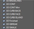
- Be sure that anything used in a surface starts with “3D” in the layer name. This helps simplify your convention so you don’t miss something on a surface that is not included in the model.
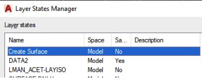
- To go a step further, use a layer state with just the 3D layers to make sure you are building with all the correct elements.
Initial Surface Build
It’s common to initially build a surface by fixing the obvious mistakes in order to get an idea of what needs to happen to make it perform correctly. But, it’s important to remember that the surface must meet the engineer’s intent and make a moving blade cut good base for paving and buildings. Here’s a suggested process:
First, decide on the layers necessary to make an initial surface. Understand that you may not draw breaklines or added spot elevations at this stage.
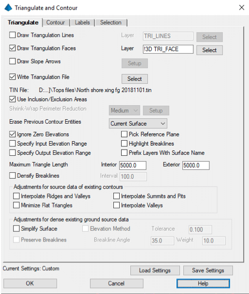
Second, open the Triangulate and Contour command and populate the settings preferred for the surface. Here are some suggestions:
- I like to initially see the faces to watch how things tin.
- When doing an FG surface, try to make a boundary. Shrink wrap is okay to start a finished surface job or for an OG topo. Get a tight boundary before sending to the field.
- Prefix Layers With Surface Name adds the name for the surface to all layers used. This is an efficient way to set all the layers in one spot.
- You can adjust the Triangle Length but I prefer to let the program make the surface then add breaklines to control length.
- Densify Breaklines is a great feature. It will add vertices at a specified interval, like densifying a polyline without the mess during production.
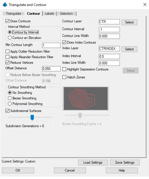
- Draw contours for a check.
- Run Contour Intervals at .1 feet to get an idea of surface integrity.
- Don’t label contours for this step in the process.
- The Selection tab allows you to pick the element type for the surface. This may help if you have un-needed element types residing on a data layer. It’s best to have layers with only types you want and not rely on selection types.
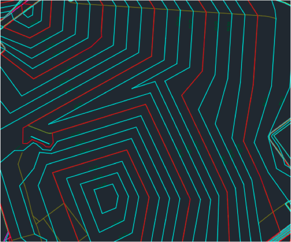
Here is the initial look at the surface:
When adding breaklines, the goal is to make the surface perform well when paved but more importantly it needs to work well with a grader blade that is tasked with smoothing things before paving.
This task takes practice and experimentation. There are no easy formulas to follow. Experiment and keep a good line of communication open with the field in order to get things working right.
Breaklines
After the first surface generation, I will add breaklines to the surface to make it look and work better. To apply this practice, I’ve outlined some general guidelines:
- A breakline is nothing more than a 3D polyline. It can be generated by the software or added by the user. It’s named because it forms a grade break in a surface where it did not exist before.
- People use too many breaklines. Don’t be afraid to try something and then delete it if you don’t like it. An example is included in the accompanying video.
- Use the same rules for breaklines on the entire project. If you do work to make one island work, do the same changes to the others for consistency.
In the video I will demonstrate breakline techniques that will get you on the right path to make the surface behave the way you want.
Working with Polylines
The most difficult part of data prep is working with 3D polylines. The hardest 3D lines to make are those associated with curbs in parking lots. We need to respect crossing contour lines and spots along a line representing the edge of paving or curb faces noted in the plans.
When a single line is properly made, we need to offset it to make other 3D lines in relation to the first. If we generate an edge of paving line, we will offset to make a curb bottom then top, and finally top back of curb.
Base 3D polyline creation
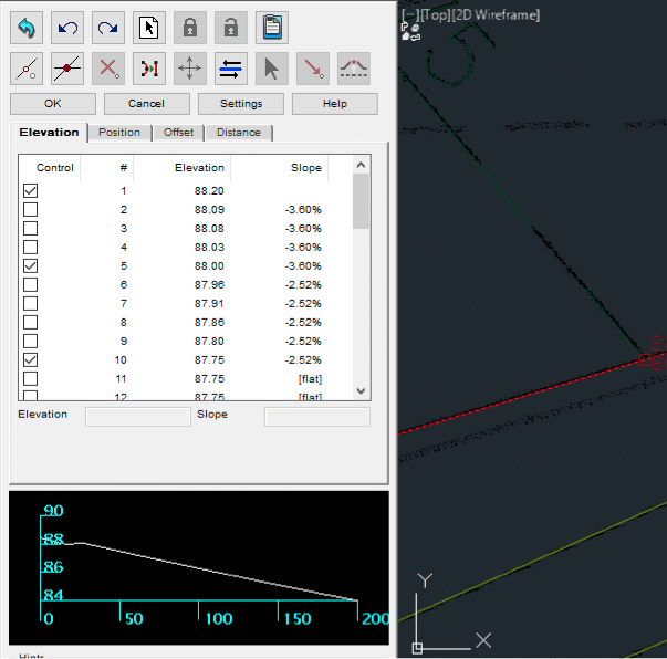
In this example, I will elevate the edge of pavement line, then move it in 3-dimensions to make the bottom face of curb and top back of curb.
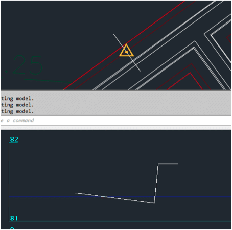
The Edit Assign Polyline Elevations command now has a real-time profile view in the command to help you visualize the resulting line.
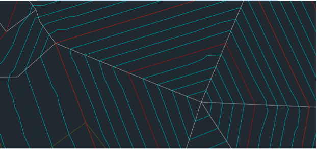
This project has contours at .25 feet. That presents its own set of problems because high and low breaks are seldom called out. This requires us to make those grade breaks. Below is a representation of one of those locations:
Always contour the site at .10 feet so that these flat spots will become obvious.
Once corrected, the surface will start to look better and perform well.
After creating a 3D line that represents what you are after, it’s now time to offset that line to get what you need. Open the Offset 3D Polyline command.
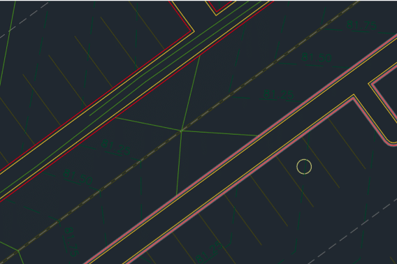
The Change Layer option can be used for the other commands. There will be layer options in the next window.
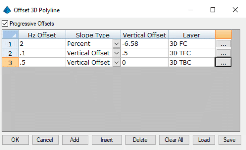
We do not build curb this way. I am doing this as an example of duplicating a fill gutter and related curb elements. With the paramaters set, click OK and pick the lines you want to work with.
The command will also work for a quick pad stepdown or a blowup to get pad limits for slab prep.
The command is also useful for a simple entry road. The command will perform the change to the centerline on both sides giving you a quick roadway.
Another advantage to the command is that it will place the new lines on a layer of your choosing. At TOPS, we like to segregate 3D lines as much as possible and this command does it for us.
The Process
With the ability to create a surface and tools to adjust things, you now have the ability to get closer to what is required in the field. I say our work is 90% science and 10% art. It does not take years to get proficient at building data. However, do pay close attention to every step and the outcome of your actions to a surface. This will help you to get better faster. Focus on areas that need work initially and then step back to be sure everything works together as a good, performing surface.