
Difference Between BIM and CAD

Difference Between BIM and CAD

With 3D technology, earthwork modelers and surveyors can view virtual models of proposed projects before the groundbreaking work commences. Different types of software can generate such visualizations, and this has led to the BIM vs. CAD modeling debate. Both options have their benefits and supporters.

For anyone new to these software tools, it’s important to be able to make an informed BIM and CAD comparison. Therefore, it is crucial to understand the pros and cons of BIM and, likewise, the pros and cons of CAD.

Make a Precision Decision with TOPS 3D Modelling

Get ahead in your construction initiative with TOPS. We employ a team of experts to develop 3D machine control models, ensuring a clearer, more precise vision for your project before construction commences. Using TOPS provides easy work order creation and thorough project visualization.

Launch Your Project Success with TOPS

Understanding BIM (Building Information Modeling)

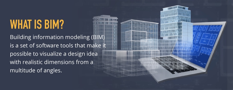
Building information modeling (BIM) is a set of software tools that make it possible to visualize a design idea with realistic dimensions from a multitude of angles. With BIM, design teams and work crews can have a virtual experience of a building, road, bridge or monument before the structure is physically constructed. For all the parties involved in the conceptualization and construction of a structure — including earthworks and surveying crews — BIM provides the following benefits and features:

Preventing Conflicts with BIM

BIM tools allow earthwork teams to determine whether any clashes might occur between a proposed design and the underlying conditions of the site in question. For example, if a building would need deep plumbing yet the ground being excavated sits over thick roots and rocks, these discoveries can be factored into the design plans to avoid issues down the line.

Reducing Errors Through BIM

BIM technology makes it possible to catch any errors that initially appeared in a proposed design before the construction work goes into effect. For example, if earthwork crews discover that the dimensions of a proposed building design will not be feasible at the prospective site, planning crews can take this information into account and either make adjustments or change the overall plan.

BIM in Construction: An Overview

BIM software is used by construction crews who break grounds on new lands to establish the foundations of roads, highways, buildings, bridges, monuments and structures. The software makes it possible to determine which structures will ultimately work over certain types of soil, thus making the processes involved with earthworks easier for planners and crews.

BIM for Ground Logistics Enhancement

BIM software contains a range of features that specifically outline the logistics of plumbing at a given work site. This way, planners can determine whether the stretch of land in question will be suited for the project at hand, be it a tall office building or a wide industrial facility.

Planning Piping with BIM

BIM solutions make it possible for earthworks crews to determine which type of piping will suit the stretch of land in question. The software can be used to create 3D piping designs that take into account the diameters and lengths necessary to transfer water underneath a proposed building site to the nearest reservoir.

Enhancing Collaboration with BIM Tools

BIM solutions offer collaborative tools that make it possible for earthworks teams to interact with other teams in the construction process, from designers and architects to builders, planners and investors. Collaboration tools include communication technology that works across different platforms, allowing cloud-based branches to interact with more traditional departments.

BIM and Visualization Technology

BIM tools make it possible to visualize a site in 3D and determine how a potential structure will appear from the ground up at a given site. Based on the position of the proposed structure, the tools allow earthworks and construction crews to determine how sunlight will hit the walls of the building or factory and potentially light its interiors.

Sequencing Steps with BIM

BIM software programs arrange the building process in a series of steps from the ground up, including the logistics involved for earthworks crews. The tools can be used to determine how wide the clearance will need to measure for a proposed structure and how deep the ground will need to be broken to support the height and plumbing needs of the building in question.

Exploring Advanced Features of BIM

BIM solutions go beyond 3D technology to make a full-scale planning sequence for earthworks and developers. In new and upcoming versions of the software, BIM is activating tools in 4D, 5D and 6D, giving users the ability to visualize cost logistics in tandem with design concerns. These more advanced features also make it possible for users to determine the thermal and acoustic properties of a proposed building on the site in question.
What is BIM in data modeling?

Addressing Potential Issues With BIM Software

On the downside, BIM has yet to be developed to the point of universal compatibility across all branches of the construction industry. Companies and crews that have fully embraced the technology may have problems communicating certain ideas, information and visuals with cooperating entities that still rely on older technology.

Due to the relative novel nature of BIM technology, expertise in BIM software is a relatively small field. Consequently, there are few technicians to consult when users need outside support on a given issue.

Exploring CAD (Computer-Aided Design)

Computer-aided design (CAD) is a set of software tools that allow designers to create 2D and 3D virtual models of buildings, structures, machines and parts. For surveyors and earthworks crews, CAD makes it possible to review a proposed structure before commencing work on the ground. The features as well as pros and cons of CAD can be summarized as follows:
What is CAD in data modeling

Visualization Benefits of CAD

CAD software makes it possible for designers and project developers to visualize a product or part in advance of its production. The software can be used to examine a proposed design from a variety of angles, both inside and out. Whereas conventional designs offer a flat illustration of a proposed idea, CAD makes it possible to step inside of a design and view it from a 360-degree perspective.

CAD’s Role in Improving Communication

CAD allows developers to communicate about the logistics and dimensions of a given design and make improvements as discoveries come to light. For earthworks crews in need of new tools and machines for an upcoming set of tasks, CAD provides an easy way for designers to communicate with team supervisors.

The Application of CAD in Structural Engineering

CAD software accommodates the various aspects of structural engineering. Moreover, most CAD programs offer functionalities that apply to specific industries and the various branches that the projects entail. For projects that involve railroad, tunnel or freeway construction, the design features take all the dimensions into account as the design team drafts a 3D visual of the proposed structure, which earthworks teams can then examine and use to visualize the intended finished project.

CAD for Earthworks Logistics

When the design for a proposed building, road or bridge is created on a CAD platform, the visualizations that the technology provides make it easier for earthworks crews to foresee how the finished structure will look from the ground up. This knowledge can then be compared to the findings of work teams as they survey the land in question and prepare to break ground.

Ensuring Accurate Design with CAD

CAD platforms make it possible for civil engineers to generate maps and analyze specs across a stretch of land. This research enables better-informed designs for railways and tunnels, thus reducing potential errors and costly redrafts down the line. This information can then be communicated to earthworks crews, making the overall plan more efficient and easier to bring to fruition.

Facilitating Input and Feedback

CAD platforms allow conceptualists to take a raw idea and turn it into a three-dimensional design. This allows different branches of a development team to mutually review a proposed design idea and make suggestions that can easily be implemented. If an earthworks supervisor spots an issue with a proposed design, the design engineer can immediately take this feedback into account.

The Advantages of Advanced CAD Tools

CAD software comes equipped with various design tools that facilitate ease of use and also make it possible to achieve visualization effects that would not be possible with a flat illustration. For example, both 2D and 3D CAD software contains a gripping feature that allows designers to pull, alter, adjust and reshape the dimensions of a proposed structural concept. If an earthworks supervisor reports that a road or pavement design requires a width adjustment, a grip tool can help employees quickly make those changes.

Potential Challenges When Using CAD Software

CAD software typically takes time to master, meaning that the cost of training can be high and the learning curve can be long. Moreover, the number of CAD experts is relatively small, which can make it difficult to find help if a problem arises.

For any company that has yet to migrate to a cloud server, CAD would be a step removed from that company’s technical infrastructure. As with most new technology, CAD is primarily designed for companies that are up to date on today’s more advanced systems.

BIM vs. CAD: Highlighting the Differences

A quick rundown of the features of BIM and CAD makes the two seem rather similar. So how do you compare BIM and CAD? The two have some crucial differences that make each more suitable for different types of projects. So what is the difference between BIM and CAD?

The biggest difference between BIM and CAD is the interactivity of the different dimensions during the editing process. BIM has interconnected objects, so any change that needs to be made in a building design, such as the width of a wall or corridor, can be done in a single edit. CAD does not have interconnected objects, so edits must be made individually.

CAD was developed to design virtual models for everything from appliances and furnishings to automobiles and rolling stock. CAD software tools are used to create 3D visualizations of the surrounding bodies of vehicles and tools, as well as the smaller parts that comprise the motors and fans inside each machine.
What are the differences between BIM and Cad

CAD can be thought of as a computerized sketchbook in which designs are hashed out and ultimately refined in 2D and 3D renderings. Each line works independently of one another and can be adjusted or eliminated without affecting any of the surrounding or underlying lines in the design. Therefore, if the design for a parking lot or road requires an extra three feet on one side, you can adjust the line that represents that side to accommodate the change in dimensions.

Complex CAD designs consist of numerous sheets, each with separate lines that are overlaid in a virtual file. If a design needs to be adjusted, you must adjust all the layers affected by this change individually. If a design consists of many layers that must each be adjusted in tandem with the others, making revisions can be complicated. With CAD, there is no way to synchronize the layers into a single-action item for a multi-layer adjustment.

BIM was developed more exclusively for the virtual design and multi-dimensional visualization of proposed building ideas. As such, the tools are designed to digitally render the complex dimensions of all the parts that comprise the interior and exterior of a residence, factory or office building, including the walls, stairs, doors, windows, ceilings, plumbing, wiring, lighting and ventilation.

A major difference between BIM and CAD is the interactivity of the different dimensions during the editing process. In BIM, the dimensions that comprise an object are interconnected. Therefore, any adjustment that needs to be made in a building design, such as the width of a wall or corridor, can be done in a single edit.

In BIM, the dimensions of a given detail can be synchronized to all instances of the detail in question. For example, if the windows on a building are initially designed to be 3.5’x5’ and need to be adjusted to 4’x5’, you can change all the windows on the virtual building with a single adjustment.

Deciding Between BIM and CAD: What’s Right for You?

Earthwork modeling and surveying teams can use BIM software to determine the ground dimensions of a proposed structure. Surveying crews can take a proposed building design and determine whether the chosen piece of land is right for the project in question. Earthworks modelers can then use the software to design the depths and dimensions at which ground will need to be excavated to set the foundations and build the sub-levels or layers of the building, factory, road, parking lot or structure.

For earthwork modeling, BIM tools can facilitate a more efficient flow of tasks because the software is designed to edit complex dimensions in a few steps. When all the dimensions of a construction layout are taken into account, BIM offers a more complex set of dimensions from various angles in a virtual preview. This way, all the parties involved in the construction can review the measurements beforehand and make suggestions or edits in advance of the project’s starting date.
Data preparation in BIM and Cad from Takeoff Pros

BIM software tools can be especially advantageous for earthwork modeling of designs that consist of multiple levels. For example, if a development team proposes a multi-level courtyard across an acre of land, BIM tools can be used to accurately render the dimensions of this idea. The surveying team can then review this virtual design and provide suggestions and feedback. Construction crews can then reference this final design when it comes time to break the ground for the courtyard.

Related Article: Mastering Earthwork Estimation: Techniques and Tips

Data Preparation and 3D Modeling by Take-Off Professionals

For complex site work, it’s crucial to have 3D models to preview before construction begins. Take-Off Professionals is staffed by a team of expert engineers who develop 3D machine control models for earthworks projects as well as perform construction material takeoffs. Regardless of the size and complexity of the project in question, we can prepare data the way you need it. Contact Take-off Professionals to learn more about our 3D modeling services.
Contact Us Today

The Mechanics of GPS Surveying: Methods and Applications

The Mechanics of GPS Surveying: Methods and Applications

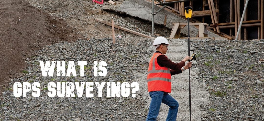
Surveying has changed substantially over the years — what used to take months of observation, measurement and geometrical calculations now takes a few hours or days thanks to the introduction of GPS technology. In fact, the surveying industry was one of the first to utilize GPS technology, recognizing the potential benefits of the technology. Today, surveying professionals rely on GPS to provide accurate and reliable data for clients across a wide range of industries and applications. Despite the widespread usage of GPS technology in surveying, however, it’s not a topic many know about — that’s why we’re here to explain the GPS surveying basics.

What is GPS?

To understand the GPS surveying process, you need to understand what GPS is. In short, GPS, or the global positioning system, is a satellite-based navigation system. GPS was first developed for military use starting in the 1970s and became fully operational in 1993. Since then, it has expanded its use to consumer and commercial applications.

How GPS Works in Surveying?

GPS uses a network of satellites, which communicate with receivers on the ground. When a receiver requests data to calculate its location, four or more GPS satellites will communicate with the receiver, sending the following information:

  • The position of the satellite
  • The time the data was transmitted
  • The distance between the satellite and the receiver

The information collected from these satellites then calculates the latitude, longitude and height of the receiver. If the receiver is moving, continuous data collection can be used to calculate the changing position of the receiver over time, which can be used to calculate speed. 

No matter the weather conditions or time, GPS can triangulate the signal and provide a location.

Leading Expertise For Your 3D Modeling Needs

With TOPS, access unrivaled 3D modeling services for your projects. Our in-house engineers specialize in preparing high-quality 3D models for site work across various operations. Trust our industry-leading, time-tested processes for timely, accurate results.

Propel Your Project With Our Expertise

GPS Surveying Compared to Other Technologies

GPS surveying uses similar technology to nearly any other GPS application — however, how surveyors use GPS differs significantly. The primary differences are in two areas — technology and usage.

  • Technology: Surveyors use more sophisticated technology than typical GPS applications to increase the accuracy of the data they collect. The receivers used for surveying are significantly more complex and expensive than those you would find in a typical car navigation system, with high-quality antennas and more sophisticated calculation technology.
  • Data Usage: The data surveyors collect from the GPS technology is used differently than in a typical navigation system — instead of using location data for navigation, the data is used for measuring between two points. These measurements are collected then stored, manipulated and displayed in a geographic information system, or GIS, for use in a survey model.

Exploring Methods of GPS Surveying

But how do surveyors use GPS to collect data? The specifics come down to the GPS surveying techniques that they use. While the basics of GPS are simple to understand, there are several techniques that surveyors use to make the most of the GPS measurements they collect. There are three primary methods of GPS measurement that surveyors use, which are listed below.

Method I: Static GPS Baseline Observations

A Static GPS Baseline is a technique used to determine accurate coordinates for survey points. Baseline measurements achieve this by recording GPS observations over time, then processing that data to provide the most accurate result.

The technique works by using two GPS receivers. These receivers are placed at each end of a line to be measured. The receivers then collect GPS data simultaneously for at least 20 minutes — the exact duration of the observation period varies based on:

  • The length of the line
  • The required accuracy of the measurements

Once all of the data is collected, a special type of software is used to calculate the difference in position between the two receivers.

This GPS surveying technique is basic but highly useful and accurate, especially when measuring particularly long distances. Because the GPS data is collected over a long period of time, and the observations are collected at the same time at each end of the baseline, the natural distortions that occur in GPS signals cancel each other out. 

Generally speaking, the accuracy of Static GPS Baseline measurements are one part per million, meaning that a 30 kilometer distance can be measured with about 30 mm of uncertainty.

Method II: Dynamic GPS Observation Methods: RTK

Real-Time Kinematic or RTK Observations are similar to baseline methods in that they are used to measure distances between a base station and a second receiver. The difference, however, is that instead of measuring the location of two points over a long period of time, RTK Observations use multiple points in quick succession.

Like the baseline method, the RTK method uses two receivers, one being a static base station. The other receiver is the Rover Station, which moves to multiple positions during the measurement period. The position of the Rover Station is collected within a few seconds and stored. Once the measurement period is complete, this data is stored and used as survey data.

RTK observations are nearly as accurate as the baseline technique, though they are limited to a range of about 20 kilometers. This method maintains a high level of accuracy by 

  • Collecting data at the Base Station and the Rover Station simultaneously 
  • Correcting data in real time

Since the exact position of the Base Station is known, so any variations can be used to correct the position of the Rover Station in real time. This method, therefore, can quickly gather survey data for smaller areas.

Method III: CORS—Extending GPS Capabilities

Continuously Operating Reference Stations or CORS operate using the same principles as the other measurement techniques described. The primary difference is that the base station is installed in a permanent known location. This allows measurements to be taken at any point in the district using the permanent base station as a starting point.

With a CORS-based system, receivers can be placed anywhere in the local area to collect data. When data collection is complete, the surveyors can combine the collected data with data from the CORS to calculate positions, correcting any anomalies to obtain an accurate position. In some cases, if multiple CORS are available, receiver data may be compared to the data of multiple CORS to achieve even more accurate results.

CORS are commonly used for major engineering projects that require continuous surveying over a long period of time — some examples include: 

  • Local government projects
  • Mining sites 
  • Tectonic plate studies for scientific organizations

One specific example is the Australian Regional GPS Network, or ARGN, which uses an online processing system to provide positions that are accurate within a few centimeters in under 24 hours. Some countries even have CORS systems that cover their entire nation, allowing for more accurate and reliable GPS positioning anywhere in the country for both commercial and consumer applications.

Benefits of GPS Surveying Techniques

GPS surveying is a quick and accurate way of mapping and modeling the physical world, from mountainous landscapes to city skylines. This versatility and utility are why GPS surveying is the standard practice for any surveying operation. Nearly any group that needs surveying done will use GPS surveying, including government organizations, scientific groups or commercial businesses. Some of the benefits these groups enjoy from GPS surveying include:

  • Flexibility: Unlike conventional surveying techniques, GPS surveying can function regardless of visibility. If survey stations are out of each other’s sight due to line-of-sight issues or weather, GPS technology can still measure their positions and provide accurate location data. This is particularly useful when surveying coasts and waterways with few land-based reference points, which is particularly helpful for nautical navigation and construction efforts. The only downside is that GPS stations need to access satellites with a clear line of communication, limiting the utility of GPS surveying in areas with trees or tall buildings.
  • Mobility: GPS systems are fairly mobile, able to be carried inside backpacks or mounted on vehicles to collect data quickly and over a wide area. In combination with CORS systems, mobile GPS survey equipment can achieve real-time data.
  • Speed: GPS technology is extremely quick compared to the old surveying techniques that relied on extensive measuring and calculations. Now, GPS provides near instantaneous data and can automatically compare that data to provide accurate results quickly, sometimes even within a few minutes. With faster data, survey teams can get quicker results and organizations can reduce decision time.
  • Accuracy: The ultimate question stakeholders are concerned about is the accuracy of GPS survey equipment. Ultimately, it depends on who does the surveying. Poor equipment and inexperienced users can negatively affect your accuracy. However, when using sophisticated GPS technology combined with top-level expertise and high-quality software, you can achieve high levels of accuracy every time.

These benefits are the primary reasons many companies choose GPS surveying specialists for their surveying needs. However, all this data is meaningless without context. For almost all industries, GPS survey data is combined with sophisticated 3D modeling to create detailed, actionable data that organizations can use to plan their projects. This 3D modeling data not only allows companies to visualize and plan projects, but it also allows for 3D model machine control for construction projects.

3D machine control uses positioning sensors to give machine operators feedback on their equipment, directing them in how to use the equipment to achieve the desired results. This technology promises to be the new standard for efficient worksite operations, improving the accuracy of construction equipment on site. For more information about GPS machine control modeling, contact Take-Off Professionals or look through our site to learn about our services.

Related Article: The Ultimate Guide to 3D Modeling in Construction

Applications of GPS Surveying

Almost any industry that needs surveying will choose GPS surveying for its high level of accuracy and utility. One of the biggest sectors using GPS technology is the construction industry — construction companies need fast, accurate survey results for their projects so they can start and finish projects quickly and confidently. Some of the biggest industries in the construction sector needing GPS surveying technology include:

  • Commercial Site Industry: Data is essential in the commercial site construction industry at every level. Commercial site construction companies need accurate, useful data and models to create cost estimates, organize their resources and improve overall efficiency. GPS survey data can help, providing accurate results quickly so that commercial site companies can make decisions that improve their profitability.
  • Roadwork and Highway Industry: Engineers and contractors in the roadwork and highway industry need accurate survey data from start to finish. Quality surveys help create accurate models, which roadwork and highway professionals can use to place accurate bids, plan projects and organize their resources efficiently to maximize their profitability. On top of it all, roadwork professionals need to get it all done quickly to minimize the inconvenience and cost to the people using those roads. GPS surveys are essential in these efforts, providing quick, accurate results for models so that roadwork professionals can get to work as quickly as possible.

The key for both of these industries, however, is choosing to work with companies that can help them achieve the results they need. Not only do they need professional surveyors, but they need next-level data modeling professionals to help create effective 3D models that can help them plan more effectively and even make use of 3D machine control. Take-Off Professionals can help.

data modeling experts at TOPS

Elevating Your Surveying Projects with GPS

When choosing 3D data modeling consultants for your next project, you need a team you can trust to get the job done right. Take-Off Professionals is that team.

Take-Off Professionals, or TOPS, is a team of knowledgeable and experienced professionals specializing in the preparation of 3D models for site work. Our team of licensed engineers, surveyors and 3D technicians handle projects for large and small projects across the commercial site and roadwork and highway industries, delivering quality results every time. Our innovative processes put quality data at your fingertips, giving you the confidence you need to:

  • Bid effectively
  • Organize efficiently
  • Complete projects while maximizing profits

Over the course of two decades, TOPS has become a data industry leader, producing an average of 1000 models per year with accuracy to three digits for imperial units and four digits for metric units. Our unique industry experience gives us insight into the concerns of our clients, allowing us to quickly adapt to client needs and address any issue so we can deliver effective, accurate and fast results every time.

On top of it all, TOPS makes your satisfaction our priority. We deliver 

  • Detailed quotes, 
  • Accurate turnaround times and 
  • Top-quality customer service for every project

We stick to our promises every time. Let us know what you need from your data, and we’ll make it happen.

Interested in learning more about our industry-leading processes and how they can help your business achieve more? Contact TOPS today by calling 623-323-8441 or through our online contact form.

Contact Us Today


X