
Update: May 12, 2022 – I got some questions after posting this article to address. As always, do not hesitate to contact me with questions.
A common mistake, “I always use the surface from the engineer and things work fine”.
Let me unpack this and discuss the reasons why you should never trust a surface you did not build.
- You are one of the lucky few who’s engineer actually understands the 3D world. This is the exception and not the rule.
- Your expectations are low. Maybe you do not have machine control. You also could think that machine control just gets you close and final grading has to be done by an experienced blade hand. If your model cannot go into a machine and cut a good grade, it’s time to up your game.
- The job may be dynamic. In other words, changes are happening so fast, the engineer actually pays attention to the model and gives you portions to work on that are close enough to get things right.
The bottom line is you don’t know what you don’t know. When an “OK” model is all that is ever delivered to the field, everyone assumes that is as good as it gets. One of the biggest sources of new business for us is when someone from one of our client companies moves to a firm that has substandard data. They point out the issues of the data and point out the advantage of quality work.
There are many reasons you may be compelled to do a quick fix on a bad surface and get it in the field. We never use an engineer’s surface sent with CAD files because we are being paid to build it correctly. From a time-management standpoint, we can build a surface faster than the time it takes to break it apart, find the issues, and put it back together. When someone finally gets the files, and crews have been on the job for three weeks, a quick (and very dirty) surface turned around overnight is better than nothing.
Everybody talks about only sending out “perfect” models. My hat’s off to you, most jobs do not get enough warning to make them pretty from the start. I am speaking of the people in the office who get the call four minutes after the CAD files hit everyone’s inbox and the voice on the other end is wondering where the model is. That is the reality we deal with. Time to figure how to make this work.
JUMP TO SECTION
The Surface Defined
When I talk about a surface, we are looking at the 3D elements that are elevated to make a model, contours, 3D lines, and points. Surfaces can be any combination of these three things. I will go through the advantages of each data type for a quick surface and what they do (alone or with other elements) to get you moving.
Contours
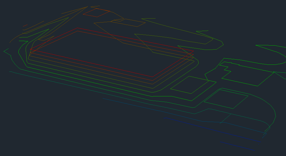
Contours are referred to as 2D lines because they are all the same elevation and still 3D because they are part of a surface. Contours undergo a lot of changes during data production but are often a quick way to get something out.
Initially, these contours do not look so bad. You need to trust me; they are a decent representation of the surface.
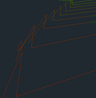
Creating a quick surface shows there are some problems. In this case we cannot send this out, work needs to be done. This may be considered work that takes too long for a quick start, but the spikes and bad information will cause more issues than they fix.
- Line density is all over the place. Some areas have long runs without anything and it is too dense in other spots. This is common for a civil 3D file.
- It needs break lines in order to make sense. A ditch is being blown over and slopes are not smooth and even.

Here is a screen shot of the improved density and some spike removal. At some point, you need to decide what a contour only surface should have. Here are some thoughts:
- This is for rough grading only. You will not get detail to get you within a half-foot, do not even try.
- Ditches and berms are easily flattened and there is no simple way to verify their existence. You need to go through the model and see if each high and low area look good.

- Streets from contours are a hot mess. That may be fine for a new subdivision road but not for a rehab project or lane additions; those are usually close to grade to start, and you may make a bigger mess doing a quick surface. You need better.
- Linking contours with break lines can solve some issues. The problem is they take time to draw and auto functions can make the cleanup harder than just connecting the dots yourself.

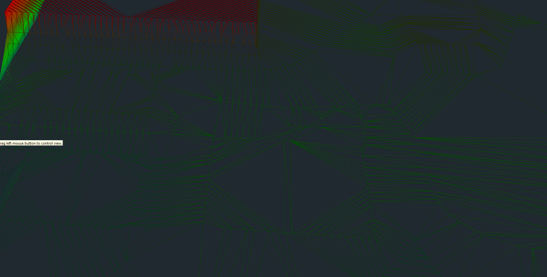
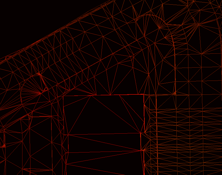
In this image the problem is with roadway contours. The triangles will link in a bad way and make a surface that not only looks bad but does not perform. There are no real easy ways out of the issue except to connect them with 3D lines.
- Edge of pavement CAD lines can sometimes be elevated as they cross the contours. The straight segments created by the function can cause crossing line and new headaches.
- Any of the three lines that make up the road, (edge of pavement, face of curb, and top back of curb) can be drawn and then offset to get things closer. The problem can spike when elevations do not match between contours and 3D lines.
One can argue that it is just a starter file, and this is too much detail. However, this can become a problem when there is not much dirt to move, and crews need more exact information.
3D Lines
Contours have one elevation their entire length. 3D lines vary in elevation and are the best way to create curbs and other road and parking lot features. Files from engineers are usually not loaded with these lines. About the only time I see them are as break lines inserted to contain features that might have been blown over during design. Without any real 3D lines to look at or adjust, you will need to make your own.
Any time I go to the effort of drawing 3D lines, I make sure all the elements I am connecting are correct. Because of this, I only use them to tame bad spots in a quick model and not for beauty. More detail will be added later when we make the actual finished grade model.
After trying not to draw break lines, the field may finally compel you to clean things up a bit to get closer to the real finish.
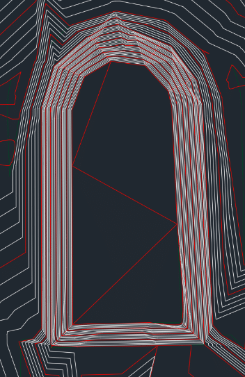
- Building pads benefit from a few quick lines to make a fence around the single elevation.
- Retention areas can benefit from a little cleanup by installing lines on corners and bottoms. These are usually the first thing done on a site so that makes sense.
- Large sheet graded areas are the first to go as well. They are not too hard to do so you can get a jump on the field by making these look nice while drilling down when building the hard stuff.
- The retention to the right looks better with some break lines. It still needs some more and the northwest corner is in the dumpster.
Points
When doing a quick repair on a bad model, points usually never enter the picture. There are times when they will come in handy though.
- When you have utilities to install, structure elevations shown as center.
- Any existing utilities and bends that can be noted by points can save a mess. 2D or, 3D is better if possible, will come in handy in the field.
- If you have control points, include them on the screen as well as a text file to upload to the data collector for an easier calibration.
Surface File

- Trimble Business Center will keep your changes to 3D faces when regenerating a surface.
- Carlson will make a new model; preservation of swapped faces is some work. It involves saving your changes and incorporating them into the new model.
- Do not be worried about removing faces and adding break lines to an engineer’s surface. Civil 3D has a lot of settings, usually CAD technicians get their finger stuck on the “make a lot of triangles” button.

- The surface on the right is not too bad. There are areas that could be improved. This may be okay to start the job but will have to be improved to make the grade.
- Here is that same general area as a finished grade model ready to work. Better triangle density and smoother contours on a gut check let us know this will do the job.
An Experiment
I performed a takeoff from an engineer’s surface that consisted of 3D faces against our model. Here are the results:
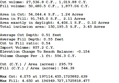
Important notes
- This is a small area at about 3.5 acres and there is a lot happening in a little spot.
- There is a couple thousand-yard discrepancy in the dirt numbers.
- The max cut and fill is 4-feet each. Their model is considerably different than ours.
Summary
“We need it now” is all too common with the fast-track world we live in. I do not want to see people waiting to deploy technology on a job. I also do not want to see dirt moved twice because somebody got a model that had too many issues. A balance must be struck. It is our job to be sure that what goes out quickly is not going to cause extra work. Be careful and check what you are sending. It is better to have the field complain they have no model than a bunch of rework.