“Software tools” is an interesting term. A tool allows you to perform work. Using the wrong tool or trying to put too many in your bag causes problems. The software tool, Trimble Business Center, utilizes commands for creating, editing and checking surfaces to help us make data that performs well in the field. We can do this quicker and more accurately than ever before but I find users get bogged down with what commands to use and when to use them. To complicate things further, as new and enhanced commands come out, users can be confused and frustrated trying to drink from the firehose of improvements.
Today I want to go over some of the commands in Trimble Business Center and talk about the best places to use them. This offering is not a training on surfaces. You can find videos on that through Trimble’s website. What this blog post will so is focus on some powerful commands that are time savers and life savers for certain situations.
I’ll reinforce some of these ideas with a video to help illustrate these concepts.
Importing a Landxml surface
Trimble Business Center has some great import options for xml surfaces. Here are some ideas:
- Never use drag and drop for an xml surface. I like to track the import options for each type of file.
- You may need to import the surface several different ways to get results you like.
- Check the file header to verify units are correct.
- If you are not certain of the quality of the surface, check detail areas for accuracy.
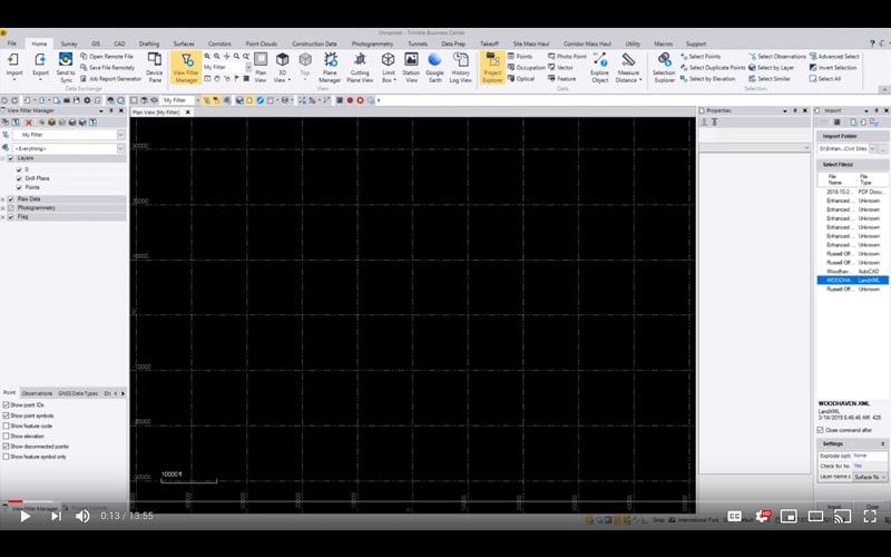
In the import command option, there are several options.
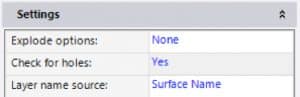
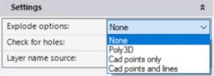
I usually don’t expand the explode options. You have several options should you decide to do so:
Try CAD Points and Lines if you want to break out surface elements. If both are present, you can have them separated to make customizing the surface easier. There is a lot more to xml. I will do an article on that particular subject in the future.
Definition of a surface
We work with a TIN (Triangulated Irregular Network) also called a DTM (Digital Terrain Model). A surface like this consists of flat triangles, often times thousands of them. The TIN produced is the representation of points, 2D, and 3D lines produced in the software during data prep. By using various commands and changing the screen elements that make up a surface, we can make it work better for our purposes.
There are options to adjust the triangles in a surface but I feel it is better to make your screen work reflect the desired outcome.
Tool Review
I want to go over some surface related commands in Trimble Business Center that are either misunderstood or have more depth than meets the eye.
Surface Properties
Trimble Business Center has a lot of features that seem to lurk in plain sight. The control available in the Properties of a surface is one of them.
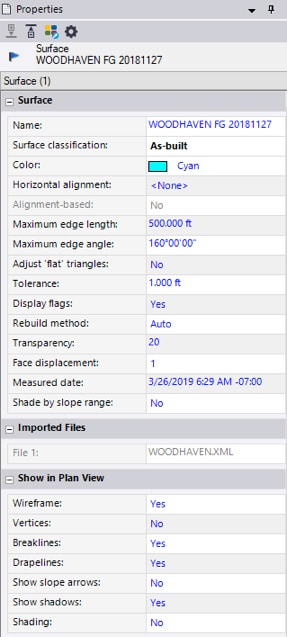
Color – Try and set consistent colors for different surface types. It helps when you open an old job.
Horizontal alignment – A quick plan-based road (not a true corridor) greatly benefits from an alignment-based surface. Use it whenever possible.
Edge settings – I will sometimes reduce these to close off errant triangles outside my desired surface before making an edge breakline. These default settings are usually fine.
Adjust flat triangles and tolerance to help reduce flat triangles on the surface generated from imported contours.
Set rebuild method to “By User” when working with large surfaces so it will not recompute with each change.
The visualization settings will help to identify specifics during the data prep process. Experiment with toggling an item off in plan and 3D view.
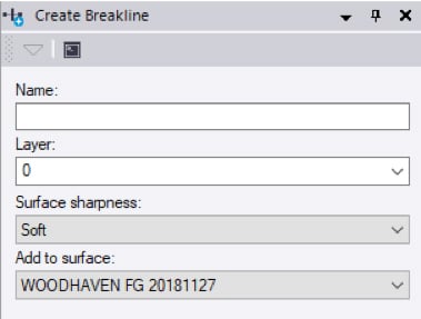
Breaklines
Any breakline is no more than a linestring that is part of a surface. The breakline command does several things.

- They can be placed on a separate layer.
- Sharpness lets you control how the line is used. Soft for grading areas and sharp for curbs and walls. Sharp and texture boundary is for material sections.
Drape Objects
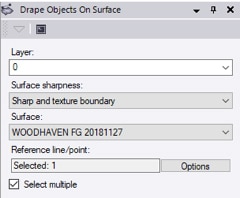
- The normal attributes for what will become a 3D linestring.
- Converts a 2D line to 3D by referencing an elevation as it crosses a TIN edge.
Another advantage of the resulting draped line is that it can be offset in 2D and 3D.
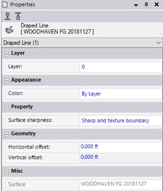
- Select the draped line, right click and view the Properties.
- You can change attributes in the Properties view.
- Offsets can be added to the line as well.
There are times this will come in handy. The video that accompanies this article will give examples.
Merge Surfaces
The idea of merging surfaces is a simple concept but is sometimes difficult for software to process. Here is an outline:
- There is a larger “outside surface.”
- I want to make or insert a surface inside the boundary of that larger surface.
- The software will trim the outside surface and transition vertically between the two.
- This is a simplified outline. Play with the command to see how powerful it is.
The issue can be at the intersection of the two surfaces. TBC has improved this process and it performs quite well.
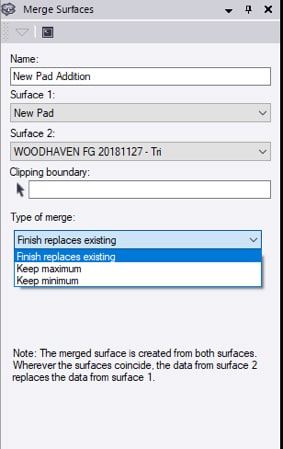
- Name is the new Surface to make.
- Surface 1 is the outside.
- Surface 2 is inside, the new work.
- A clipping boundary can be added to reduce area and file size.
- Type of merge lets you select elevation difference or the entire surface.
Sometimes there will be spikes at difficult transitions. Review the resulting surface and make minor corrections as necessary.
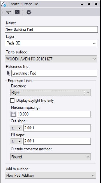
Create Surface Tie
This can be used in conjunction with or instead of the merge surface command. The command is more of a design tool and can bring a lot of smaller command pieces to one place. The most common use of the command is to place a new building or house pad to a surface and view the resulting slopes and catch points.
The reference linestring can also be open and the command works well for slopes on the outside of a surface you built as it daylights into the existing ground. I will use this for a quick haul road or simple street in a subdivision.

- This is the layer they will reside on.
- This is the surface your new work will tie to.
- Just drag and click to pick projection line direction.
- This checkbox will not show slope lines, just daylight.
- Node distance along new linestrings.
- Slopes can be ratios, percent, or a sharable slope table.
- This will make the daylight line rounded or square.
- You can add this to an existing surface. It will update the surface permanently so be careful. You can also not add to any surface, or best, make a new surface that is a combination of the tie surface and your new work.
There are more tools and ideas I will share in upcoming articles about Trimble Business Center. Get comfortable with these commands and their use in your data processing. These commands are a great way to simplify and speed up the data prep process.
Learn more about how we can help you with our 3D machine control modeling, quantity takeoff, and data preparation services.