What to Expect from Free Models
Being offered a free model to work from could potentially save time. You may even think, “Why not?” In this post, I will discuss what’s entailed when working with free models and how to determine the best approach. Use this as a guide on how to look at a model you’re given and verify that it’s what you want. I’ve outlined a process to make it easy for you to verify if the data is ready for the field.
The Surface
Most of the time when you are offered a surface file, it’s something the engineer has produced. The quality of the surface file can range from “ready-to-go” to just useless. Two explanations could be the engineering firm may have built the surface file to be used in dirt calculations (takeoff surface) or created the file for a presentation. You will not want to use either one.
The Takeoff Surface
When providing numbers for permitting and dirt use, the engineer will make a surface file. For the purpose of a takeoff, it does not need to be exact. I have long stated that if you use your takeoff surface for data, you’re spending too much time on the takeoff. Another more important reason to be wary of an engineer’s takeoff surface is that it’s generally done at the first draft of the site. Comments from agencies, owners and the utility investigation will make changes to the plans that affect the surface rendering making the takeoff surface unrelated to the final plans.
Related Article: Quantity Takeoffs in Construction: A Comprehensive Guide
The Presentation Surface
More engineers are using 3D design to produce better projects. A 3D model gives the stakeholders a better idea of what the finished job will look like. When the vertical components (e.g., buildings) are added, the improvements made to the appearance and function are easier to see and quick to update. As the design matures and gets in ground stage, 3D model updates usually stop and the focus switches to printed plan production and permitting. This is understandable and normal in the paper plan world we still live in. It will take many years for 3D models to become part of the plan submittal. In post approval, we see highway projects requiring 3D model submission for approval before paving. Civil sites are not there yet.
Surface Review
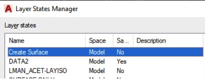
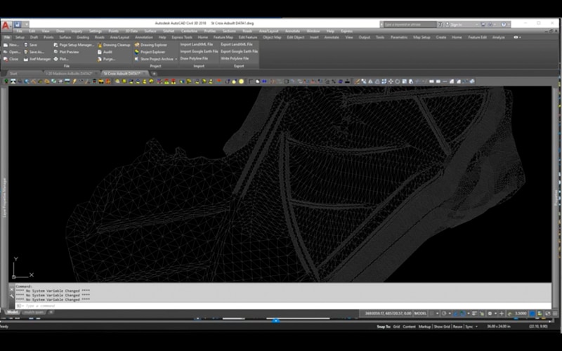
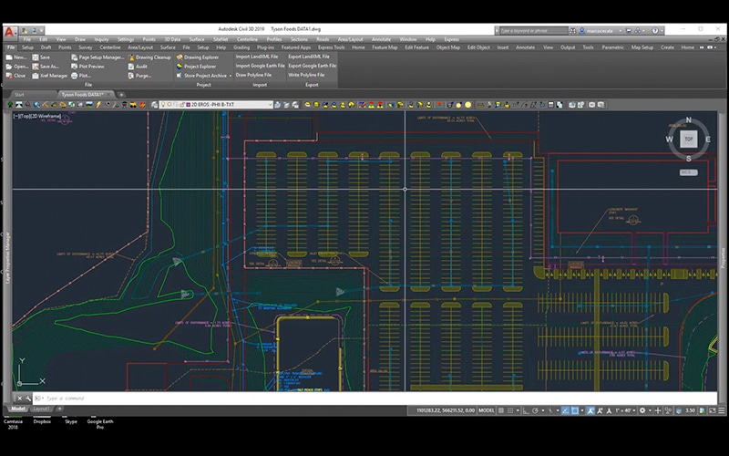
When you receive a surface file, there are several steps to confirm if it’s even worth loading in the rover. Time is money and it generally takes longer to review a surface file than to just start from scratch. To use a surface file, you’ll need to take the file apart and then reassemble it to verify it’s accurate. This will take almost double the time versus creating the file. At TOPS, we never use an engineer’s surface file for data. Our clients ask us to make it for them. The following is the process I use to review a client surface file:
- Inspect the file size. A surface file may be big because it represents a large area. I often see smaller surface files that are too dense and contain a lot of unneeded triangles that are hard to remove or filter.
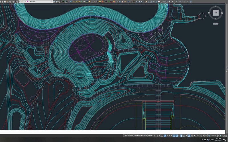
- Determine whether the surface is dense enough. If the triangles of the TIN are spaced too far to indicate correct details this affects accuracy. The file may get you through rough grade but a better one will be needed for finish.
- Confirm the version. Many times the surface file is used for one of the purposes I outlined above and is an older version of the plans. We see this a lot. A quick way to tell is to look at the deltas on the plan revision box and see what type of changes happened since the file was prepared.
When the surface file has passed the above inspection, it’s time to review the quality of what you have. Be aware that any review and work you do short of a full build of the surface file can still mean problems. Be cautious.
Review Process
Always start with the most difficult parts of a surface file to model. I’ve outlined what to look for on the different project types, as well as, Field Model Requirements that can require models built for surfaces other than finish.
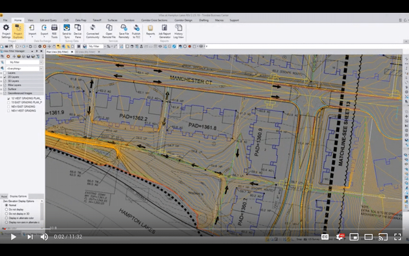
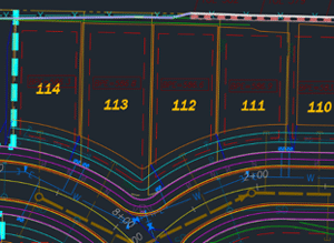
Civil Sites
- Look for flat building pads and smooth sidewalks from there to the curbs.
- Go to the parking lot and verify the storm rims are correct and look at the slopes to them. Are they smooth and in the correct direction?
- Entrances and exits need to match up to the existing pavement. This is usually finalized in the field. Just look for big discrepancies.
- Finally, review the retentions and landscaped areas. Check the volume of retention against the called-out requirements in the plans. Often these must change during the design process.
Field Model Requirements
- Pad Blowups
- Subgrade surfaces
- Paving overbuilds for curb machines and base
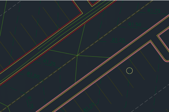
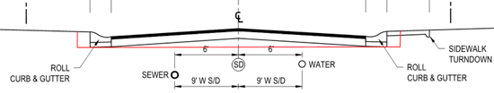
Urban Streets and Subdivisions
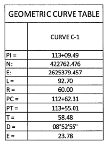
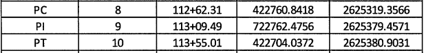
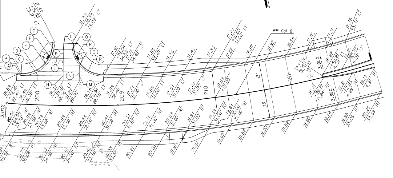
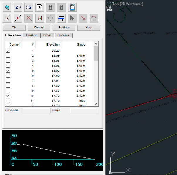
- Verify the COGO (Coordinate Geometry) of the centerlines.
- Check the cross slopes of the streets.
- Review the intersection quality. Verify the details shown match the plans. If there are no details present, look for water movement and drivability.
- Verify the sidewalk and parkway (e.g., grass) areas that are critical to slope.
- Confirm the 2D and 3D properties of lot and pad dimensions.
Field Model Requirements
- Gut section (over-excavation of streets for fill by utility spoils)
- Subgrade surface
- Matching roadways into field shots taken at sawcut lines
- Utility trenches
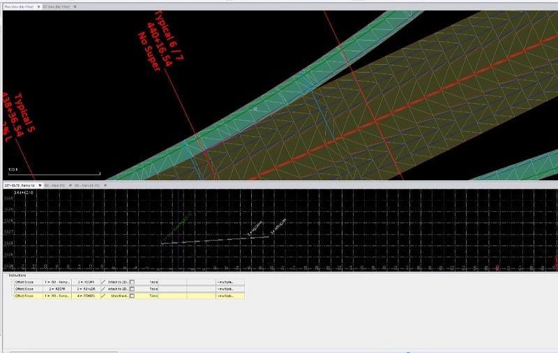
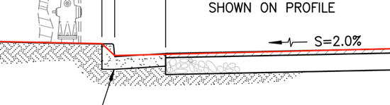
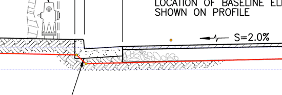
Highways
- Verify horizontal and vertical alignments.
- Confirm roadway width. Includes widening and intersections.
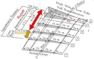
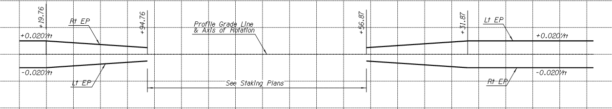
- Review cross slope and super elevated curve transitions.
Field Model Requirements
- Widening base for track grade
- Subgrade surfaces
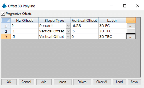
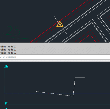
- Non-conforming subgrades, this is where the subgrade is not parallel to the road surface or the break point of the subgrade is not at the road centerline.
- Catch points that need to meet a field generated topo
It is possible to use a surface from an engineer as a basis measure of quality. However, when the smallest doubt arises, it is best to build it so you really know what you have.