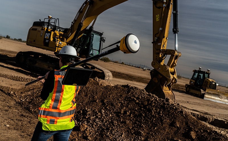
This update will go over the newer concepts for design/build on a civil site.
These concepts have done a lot for large roads and in the vertical world where tenant build outs change daily. Generally, engineers that do not have enough staff and are worn down will welcome input from you and your staff. There are several considerations you need to address for this type of relationship.
Beware of a CMAR (Construction Manager at Risk) projects. They can be profitable but need to be fully vetted on the front end. Change orders are usually not an option. These contracts are an effort by the owner to get fixed price work so know what the project entails.
For the civil portion of a project that is done in close contact with engineers and owners, things can go fast. Changes are easily approved, so be sure you propose answers. After all, this is a team job, and you will be tasked with solutions that keep the job on schedule and budget.
Money becomes more transparent. The billing is at cost plus, or a fee above agreed upon operating and materials costs. It’s not a problem, just a different approach to billing and verifying pricing. Price increase adjustments for material cost increases need to be included.
We have all been there. Get a set of plans, open them, take a look, and wonder what possessed the team responsible to perform the way they did. I started my career in the offices of a developer/builder. I got to see firsthand how the process goes, as well as the changes that must happen. The journey often ends up with something completely different than originally planned.
Development Types
There are two types of builder groups; public and private. For this discussion we will look at private work. Private work can be further broken down into commercial and local. This article covers commercial builders.
Commercial Development
In the civil construction world, commercial development relates to projects done by a large company in different geographic areas. Think of a big box store or restaurant.
Here are some general specifications:
They have centralized operations and often work on sites they may never visit.
Their staff does a lot of projects. Operations are streamlined and efficient. When they get busy, questions can sometimes take too long to get answered.
They have little emotional investment in the process.
Deadlines and opening dates are the only thing that matters. I have seen corporate firms do full redesigns to placate local building officials without blinking an eye.
They are not afraid to spend money to get things done. The fast-track construction concept came about just for big box retail.
They are not used to dealing in your area. Try not to suggest, “we do it this way around here.”
Junior people handle stuff first. Get used to clearly explaining an issue so the next person up the ladder has all pertinent data.
The Process
The biggest factor in commercial work is the time from land acquisition to opening day. Pay and bonuses for employees involved are measured by expediency of their work. A month delay for a big retailer translated into hundreds of thousands of dollars in lost revenue. They still have a bottom line. Quick decisions to problems are important to keep in mind.
Over 15 years ago, I wrote an article for a magazine that included the thought, “all the good dirt is gone.” The nice flat building sites with well compacted soil and no garbage were all developed and all that is left is the stuff that is expensive and difficult to work with. The land is acquired by the company and the process begins. For this part, both commercial and private work follow the same course.
The selection of an engineering firm takes one of two roads. The company has a nationally registered firm, meaning they have people with a license in each state they work in. The other track is to contact a local firm that has experience in the area to get things going. I have not seen much difference in the choice. An advantage of a local firm is that if you get the job, communication could be smoother.
Next, a survey of the property is performed and submitted to the engineer and owner. These will be ALTA Surveys. This means they conform to the American Land Title Association guidelines that follow strict standards for real estate transactions. I remember a job involving a McDonald’s restaurant in Las Vegas that had three surveys performed to verify the plot. The land was priced by the square foot, so every little bit made a difference for all involved.
The survey is just 2D and clearly outlines the property boundary. At the same time, a topography map is usually made to provide the engineer with a starting point.
Site Specifics
We all know what a Wal-Mart or Home Depot looks like. When it comes to the area surrounding the building, this is where things must conform to the site purchased. The process being backwards, at least to us civil types. The footprint of the building is decided. How big a structure needs to be built to supply the anticipated traffic. From there, the civil engineer takes the job. There are fixed and fluid variables that enter into the site design equation, and many of them are decided by local codes.
Drainage needs to be sorted first. Knowing how big the building is, how much of the project do we need to dedicate to drainage? Most local codes will let you work in cubic feet of storage, meaning deeper basins that take up less area. Some require a percentage of the site have allocated green space, which also can be retention basins.
Number of parking spaces may be called out by ordinances. Handicap spaces are also controlled that way. This is the reason you may see a lot of accessible spaces in some parking areas and not many in others. Local codes adjust that. The only requirement is they do not allow less density than the ADA guidelines outline.
Access is next. We would love every entry to have a nice long decel lane, wide access driveways, and plenty of entrances and exits. The site will restrict this as well as the roads they enter.
The owner and engineers will need to look at the aesthetics and curb appeal of the project. Nobody wants to enter an unwelcoming site. Green space, trees, and easy access are all key.
There is no such thing as a great parking lot design. All ideas have drawbacks. Make something easy to navigate and somebody will find a way to gum things up. Useable area has the biggest impact on one way or two-way lot lanes, nothing else.
With these less than desirable plans in your hands, you bid the job. The hard bid was won, and it is time to work. I have seen many a small to medium contractor do a bang-up job for an owner and get asked to do more on a negotiated basis. Keep that in mind when you look at this type of work.
My best advice is to submit your concerns right after being rewarded the job. You already have the list of concerns that was made during the takeoff, estimate, and bid where contradictions and confusing details were presented in the plans so this should be easy. Addressing concerns at the start will accomplish two goals, it shows that you’ve studied the plans well and gives you the chance to bail if you do not like their answers.
Change orders are normal. Do not hesitate to fully explain the problem and solution. Your submission will most likely pass through two or three people before it gets approved.
Fully explain the issue requiring the change order.
Propose a fix and the cost associated. Remember, never ask a question without providing your own best answer.
Make your submittal stand on its own. In other words, if I read your change request and have any questions, you did not do your job well enough.
Site selection, design and construction are all handled by different people. Seldom does one person follow a project through. Make sure everything is written down. Communicate with all stakeholders so that there is no misunderstanding when things get handed off.
Update: May 12, 2022 – I got some questions after posting this article to address. As always, do not hesitate to contact me with questions.
A common mistake, “I always use the surface from the engineer and things work fine”.
Let me unpack this and discuss the reasons why you should never trust a surface you did not build.
You are one of the lucky few who’s engineer actually understands the 3D world. This is the exception and not the rule.
Your expectations are low. Maybe you do not have machine control. You also could think that machine control just gets you close and final grading has to be done by an experienced blade hand. If your model cannot go into a machine and cut a good grade, it’s time to up your game.
The job may be dynamic. In other words, changes are happening so fast, the engineer actually pays attention to the model and gives you portions to work on that are close enough to get things right.
The bottom line is you don’t know what you don’t know. When an “OK” model is all that is ever delivered to the field, everyone assumes that is as good as it gets. One of the biggest sources of new business for us is when someone from one of our client companies moves to a firm that has substandard data. They point out the issues of the data and point out the advantage of quality work.
There are many reasons you may be compelled to do a quick fix on a bad surface and get it in the field. We never use an engineer’s surface sent with CAD files because we are being paid to build it correctly. From a time-management standpoint, we can build a surface faster than the time it takes to break it apart, find the issues, and put it back together. When someone finally gets the files, and crews have been on the job for three weeks, a quick (and very dirty) surface turned around overnight is better than nothing.
Everybody talks about only sending out “perfect” models. My hat’s off to you, most jobs do not get enough warning to make them pretty from the start. I am speaking of the people in the office who get the call four minutes after the CAD files hit everyone’s inbox and the voice on the other end is wondering where the model is. That is the reality we deal with. Time to figure how to make this work.
The Surface Defined
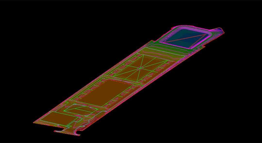
When I talk about a surface, we are looking at the 3D elements that are elevated to make a model, contours, 3D lines, and points. Surfaces can be any combination of these three things. I will go through the advantages of each data type for a quick surface and what they do (alone or with other elements) to get you moving.
Contours
Contours are referred to as 2D lines because they are all the same elevation and still 3D because they are part of a surface. Contours undergo a lot of changes during data production but are often a quick way to get something out.
Initially, these contours do not look so bad. You need to trust me; they are a decent representation of the surface.
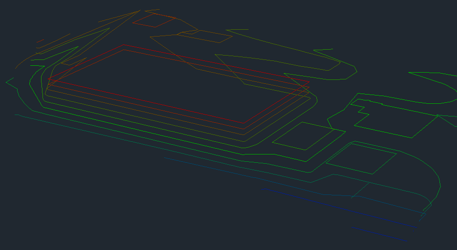
Creating a quick surface shows there are some problems. In this case we cannot send this out, work needs to be done. This may be considered work that takes too long for a quick start, but the spikes and bad information will cause more issues than they fix.
Line density is all over the place. Some areas have long runs without anything and it is too dense in other spots. This is common for a civil 3D file.
It needs break lines in order to make sense. A ditch is being blown over and slopes are not smooth and even.
Here is a screen shot of the improved density and some spike removal. At some point, you need to decide what a contour only surface should have. Here are some thoughts:
This is for rough grading only. You will not get detail to get you within a half-foot, do not even try.
Ditches and berms are easily flattened and there is no simple way to verify their existence. You need to go through the model and see if each high and low area look good.
At the right is a mess that should be a nice retention area.
Streets from contours are a hot mess. That may be fine for a new subdivision road but not for a rehab project or lane additions; those are usually close to grade to start, and you may make a bigger mess doing a quick surface. You need better.
Linking contours with break lines can solve some issues. The problem is they take time to draw and auto functions can make the cleanup harder than just connecting the dots yourself.
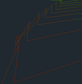
In this image the problem is with roadway contours. The triangles will link in a bad way and make a surface that not only looks bad but does not perform. There are no real easy ways out of the issue except to connect them with 3D lines.
Edge of pavement CAD lines can sometimes be elevated as they cross the contours. The straight segments created by the function can cause crossing line and new headaches.
Any of the three lines that make up the road, (edge of pavement, face of curb, and top back of curb) can be drawn and then offset to get things closer. The problem can spike when elevations do not match between contours and 3D lines.
One can argue that it is just a starter file, and this is too much detail. However, this can become a problem when there is not much dirt to move, and crews need more exact information.
3D Lines
Contours have one elevation their entire length. 3D lines vary in elevation and are the best way to create curbs and other road and parking lot features. Files from engineers are usually not loaded with these lines. About the only time I see them are as break lines inserted to contain features that might have been blown over during design. Without any real 3D lines to look at or adjust, you will need to make your own.
Any time I go to the effort of drawing 3D lines, I make sure all the elements I am connecting are correct. Because of this, I only use them to tame bad spots in a quick model and not for beauty. More detail will be added later when we make the actual finished grade model.
After trying not to draw break lines, the field may finally compel you to clean things up a bit to get closer to the real finish.
Building pads benefit from a few quick lines to make a fence around the single elevation.
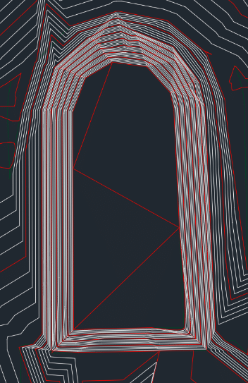
Retention areas can benefit from a little cleanup by installing lines on corners and bottoms. These are usually the first thing done on a site so that makes sense.
Large sheet graded areas are the first to go as well. They are not too hard to do so you can get a jump on the field by making these look nice while drilling down when building the hard stuff.
The retention to the right looks better with some break lines. It still needs some more and the northwest corner is in the dumpster.
Points
When doing a quick repair on a bad model, points usually never enter the picture. There are times when they will come in handy though.
When you have utilities to install, structure elevations shown as center.
Any existing utilities and bends that can be noted by points can save a mess. 2D or, 3D is better if possible, will come in handy in the field.
If you have control points, include them on the screen as well as a text file to upload to the data collector for an easier calibration.
Surface File
Sometimes you won’t get the pieces used to make up a surface, you just get the triangles. With Civil 3D files opened in that program, the individual parts can be extracted as well as other important data to make the job of the model from the engineers clean up easier. When all you have to work with is a mass of triangles, you do not have a lot of options for greatness.
Trimble Business Center will keep your changes to 3D faces when regenerating a surface.
Carlson will make a new model; preservation of swapped faces is some work. It involves saving your changes and incorporating them into the new model.
Do not be worried about removing faces and adding break lines to an engineer’s surface. Civil 3D has a lot of settings, usually CAD technicians get their finger stuck on the “make a lot of triangles” button.
The surface on the right is not too bad. There are areas that could be improved. This may be okay to start the job but will have to be improved to make the grade.
Here is that same general area as a finished grade model ready to work. Better triangle density and smoother contours on a gut check let us know this will do the job.
An Experiment
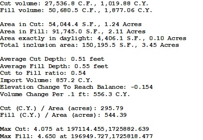
I performed a takeoff from an engineer’s surface that consisted of 3D faces against our model. Here are the results:
Important notes
This is a small area at about 3.5 acres and there is a lot happening in a little spot.
There is a couple thousand-yard discrepancy in the dirt numbers.
The max cut and fill is 4-feet each. Their model is considerably different than ours.
Summary
“We need it now” is all too common with the fast-track world we live in. I do not want to see people waiting to deploy technology on a job. I also do not want to see dirt moved twice because somebody got a model that had too many issues. A balance must be struck. It is our job to be sure that what goes out quickly is not going to cause extra work. Be careful and check what you are sending. It is better to have the field complain they have no model than a bunch of rework.
For this article I will go through the evolution of the way things were to the way they are today when working with local coordinates. The information is presented as fundamentals to your understanding of how GPS surveying works on a job site. Not being familiar with these concepts could cause issues along the way as you work through working with local coordinates.
Talking Survey Coordinates
When performing a layout and surveying with a total station, level, chain, or a combination – equipment jobs are assigned coordinates based on a random northing and easting. For smaller sites, it seems the most common starting coordinate is 5000, 5000. The “bottom, left corner” would be the starting location of the assumed coordinate system so the numbers going to the north and east would get bigger. This also leaves room to the south and west of the start point to avoid negative coordinates – more on that later.
In the past, points that were to be laid out on a job were assigned coordinates that conformed to where the arbitrary coordinates started. This system works well, but we haven’t used it in years. Almost all our GPS based jobs are located on state plane coordinates. Later in this offering I will talk about the mechanics of a localization or calibration. It’s the same thing but different names depending on the brand of equipment you use.
Enter GPS Surveying
In the early days of GPS survey, localization was carried out by aligning GPS coordinates with the local grid assigned usually during the initial survey. Things worked well and the equipment wasn’t confused by the numbers. Somewhere along the way, people realized that their data could be monetized if it could be placed on a map in the correct location. A surveyor working in a town or city could use the control from surrounding jobs to locate control for a new job. That information would be worth money to both the city and GIS providers to enhance location services.
The shift to map coordinates was not immediate. One of the reasons was surveyors did not want their control being used for a neighboring job that they were not being paid for. Many also stated the additional liability of somebody using their state plane points and then something going wrong. It may not be their problem but that would be decided by lawyers, so it was best avoided.
Autonomous GPS receivers used in cars and hiking units are incredible. We can geolocate within a few feet. This was not always the case. Selective Availability (SA) was an intentional degradation of public GPS signals implemented for national security reasons. In May 2000, the U.S government discontinued its use of Selective Availability to make GPS more responsive to civil and commercial users worldwide. When SA was in use, the best autonomous units could achieve was 50–100-foot accuracies. Great for travel or hiking, not so much for precision. Without doing a deep dive, we employed a base station to triangulate signal locations to give us the accuracy we see today.
How do we get the GPS to see us in state plane coordinates? A localization is required to sync these two different measurements. What you are doing is telling the GPS, “When I am at this Latitude, Longitude, and GPS height, tell me I am at this northing, easting, and elevation.” There are a couple of things to note in this statement:
Latitudes, longitudes, and height are what the GPS is reading all the time. Our screen shows the coordinates we want it to.
The units all use meters in the background, converting them to decimal feet at the end for viewing on the screen.
It is important to note that I used the word “height” when talking GPS and elevation with state plane coordinates. GPS uses a mathematical ellipse to establish the not regular sea level. Your elevation will always be different, sometimes over 100 feet. Be sure you are talking about the correct type of tall.
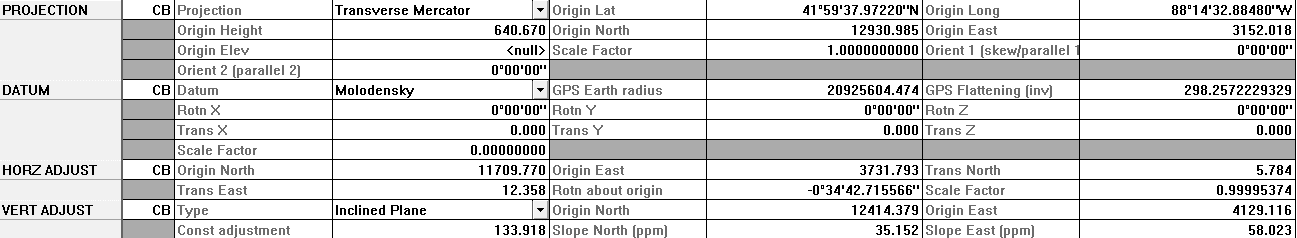
Above is a shot of a few lines of a site calibration. This is the Trimble data collector file, (.dc)
The origin Lat/North are in the first two rows. This is how we tell the GPS to give us desired coordinates for latitudes and longitudes.
The horizontal adjustment is needed to force the points to match up. The translation and rotation of the points will usually never be an issue to you. When things do not work right, then you get deep into this data.
Scale factor is usually the only thing you need to pay attention to. If you have a 1 followed by four zeros or four 9’s following a decimal point, then you should be good.
The GPS must be mathematic, just like the ellipsoid used for mean sea level, your job gets tilted on an inclined plane.
The vertical adjustment shows the slopes to the north and east from an origin point in parts per million. In this case, the slope to the east is .000058%. This is the reason you need to have multiple calibrations on longer jobs. In one mile, the vertical on this job could be off by three tenths.
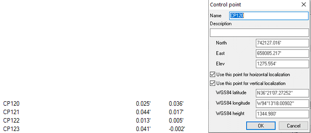
Here is a control file from a Topcon controller. I drilled down to control point 120 and was given the following information:
The northing, easting and elevation of the point are either keyed in manually or imported from a text file.
Upon occupying the point, the relationship is made.
The residual values, (accuracy) are within my desired tolerance so I checked both the vertical and horizontal use in the control calculations for this point.
Note the almost 70-foot difference in the local elevation and the GPS height.
Coordinate Confusion
Things do not always go according to plan. When something does not look right, it is probably wrong.
US and International feet
A source of confusion and sometimes great expense is that in the United States we use two different measurements for a foot. The difference is 2-feet per million feet. The problem is that state plane coordinated can be in the millions so a mix-up can put you several feet from your intended target. Six states use the international foot with the balance using U.S. feet.
States using International Measurement are:
Arizona
Michigan
Montana
North Dakota
Oregon
South Carolina
To make things even more complicated, the U.S. foot will be deprecated as of January 1, 2023 making the international foot the standard. There is a lot of commotion going on around the proposed change and as far as I can tell, it will happen. The biggest argument is that a majority of people and real estate use the U.S. foot, why not change to that? Time will tell, stay tuned.
A fun website
To help you navigate to any place on earth (and your big jobsite) easily, I have been using an app called What 3 Words, https://what3words.com. The world is now broken down into 3-meter squares. This has really helped emergency services as well as friends who can never quite get directions right. We use it in the field to tell people where we are meeting. It sure beats “go to the job trailer and keep driving.”
Over the past 15 years we have had to sort through different types of 3D data for a job. In this presentation, I will go over some issues we find when dealing specifically with roadway rehabilitation. Issues can come up with any type of construction data. However, roadways are more critical. Maintaining traffic and smoothness requires higher precision than a new parking lot for a retail site.
The major interstates are in place, but in different areas they are getting widened and constantly repaired. Larger arterial roads get re-routed and widened as population changes occur. These and other factors mean that you need to be efficient at this type of work as there is a lot of it out there.
In our hypothetical case, we are milling, filling, and widening a road section. Here are the various types of data you could receive for existing conditions on a job.
GPS Rover Shots
The project has been worked on for a while and uses GPS to get things organized. The job is calibrated, and work has been done in the field. Some topo shots have been taken of the edge of pavement, so the new lanes have a vertical to attach to. The main issue here is the quality of the data.
How good is the calibration?
Did the operator check the known control?
How long was the point occupied? In heavy highway work, long observations are dangerous.
Was the pole plumb?
How recently was the rover pole calibrated?
There is no way to know this information by reviewing the metadata of a shot or a session. No assumptions can be made regarding quality. Hopefully, there is an opportunity to make a surface of the data to check accuracy. Yes, there can be issues with the GPS performing the check. Where precision is an issue, I do not fully support GPS only information.
GPS survey information gets used a lot, and we work with it all the time. No need to stop trusting GPS rover data. You do need to be aware of the problems you may encounter when counting on it for high precision. Fully trusting GPS data for a highway reconstruction will most likely not get a rideability bonus.
I have been doing topo work with drones since the infancy of using drones to collect data. Drones are a great tool but must be used properly. In addition, expectations must be managed to provide accurate information within tolerance.
The best accuracy one should expect from a drone topo is half a tenth (.05’). That is great news for doing interim dirt topo(s) and pre-job topo(s) on mostly cleared land. Photogrammetry software does not perform well with a single-color surface. We often have problems with sand and dirt work that is smooth and monotone. White and asphalt paving both have the same issue. It is difficult to get any consistency with photogrammetry modeling on these surfaces. Things get worse when you try and extract curb data, and elevations jump. Photogrammetry techniques cannot be used to obtain paving elevations for rehabilitation and widening.
Over the years we have provided drone topo(s) on heavy highway projects. That information is used as part of a hybrid surface. The drone is great for slopes and medians while a higher accuracy method is employed for paving areas.
Drone LIDAR
I am excited about the use of drones for LIDAR (Light Detection and Ranging, 3D Laser Scanning). We have relied on full scale aircraft mounted LIDAR for years and are happy with the results. The problem with drones and LIDAR is vibration. The measurement is taken and by the time the unit gets a return, the vibration has put the unit in a different location. Yes, the change is small but enough to cause inaccuracies that are being improved upon every day. I have visited some white papers on new offerings and am confident the issue will be sorted soon. I feel within a year, the process will be accurate and repeatable. Within five years of that prices will drop so this will become the norm.
Mobile LIDAR
Many of us have seen mobile LIDAR units at tradeshows. The late model SUV with a GPS antenna and a big scanner mounted on top is impressive and expensive. I get a lot of calls and emails on this topic, and the manufacturers know this needs to be solved.
Mobile LIDAR is a great solution, but the issue is in the cost. Figures can vary based on options and software but $750,000.00 is a good estimate all in. That’s too much money for a contractor, so leaving it to survey and mapping companies is a better option. I have consulted with numerous firms considering the purchase of this equipment. Here are the facts.
It is expensive.
There is a steep learning curve.
People will need to be hired to operate and maintain the gear and vehicle. Usually two expensive office/field operators.
To gather and process the huge amounts of data collected, you will need:
Expensive field laptops
A lot of solid state portable hard drives. This data is easier to express mail than upload in many cases.
An office computer(s) to do initial processing and reduction to specified densities. This takes a long time and can use up to three powerful desktop units to keep various jobs on schedule.
Finding people to buy data. This unit needs to be moving all the time. The crew will be on the road a lot. Depending on population density, a 500-mile radius may be needed to make this profitable.
As you can see, quality data comes at a cost. When hiring the service to be done for you, expect from 4-10 thousand dollars a mile depending on the job and distance from the unit’s home base as well as the project size.
Ground Based LIDAR
Currently, the use of this technology is striking the balance between accuracy and cost, and it comes with a price. Ground based LIDAR can be as accurate as necessary for paving work. As with any technology, especially one we are expecting high precision, conditions need to be met.
The job needs to be localized and the quality of that must be verified. LIDAR needs to be setup over known points. This is not necessary for all scans, as they will register to each other. On any linear project like a roadway, there needs to be a high number of good control points for verification and setup.
Operator error is the main issue we see for poor data. It is easy to use but setup and operation are procedural. If one step is missed in the process the data quality will suffer.
These instruments are sensitive and need to be handled carefully. If a drop or a fall happens and the unit is not checked, data quality can suffer.
Training is not too difficult. One person can do the work and needs to be responsible for the unit.
Prices are dropping to the point where a contractor can pay for a unit with the profit from a job or two. Rental is an option as the dealers know you need it and may not want to purchase.
File sizes are going to be big, so be prepared for a lot of storage space.
Scan only what is needed. We see a lot of scans including trees. We are doing roads, not lumber.
In conversations with friends and clients around the country, I am hearing the same story more often: things are busy, and we are hiring. Most of the applicants are younger and computer savvy, why are they so slow to learn? A fair question that begs a deeper dive. I will try to go over the process we recommend to our clients that might help you as well. This is not a “how-to” for all things GPS but rather a linear walk through of the issues surrounding training and eventual competence of a recruit.
Remember When
One of my favorite thoughts when training a new person is that “we all start out as beginners.” After spending some time in the field and encountering your share of problems it’s easy to forget the growing pains. A common reset I use to make this obvious is to hammer a nail with my non-dominate hand. It is awkward, slow, and not pretty. That is exactly what the new person at the controller feels like. Pause and consider the person you’re training before blasting through a menu you know by heart.
Most of us were trained by someone taking us to the field, or parking lot with a dummy job, and going through the paces to get some basics down. From that point everything we did was learned by trial and error. On a jobsite where machines are moving and progress needs to be made, you cannot wait for a visit from a trainer. We had to make things happen. The process was slow, but over the months and years things got easier.
Who Do I Hire?
My second most asked question is, “What type of person should I hire for (fill in the blank) position?” I get asked this for office and field people. My answer has been consistent over the years and goes something like this: “It is easier to teach a person with field experience the mouse clicks than to try and instruct a computer super-user civil construction.” Now that you have my recommendation, here are the tips for finding them.
Promote from within. A known level of experience and reliability that may need more training is a safe bet than somebody who looks good on paper.
Somebody who is eager is better than someone with more skills that needs to be talked into the opportunity.
Be realistic when recruiting. “Oh, it’s easy” is not reality.
Just about everyone in today’s job market have enough computer skills to navigate office and field software. The quest is for a mind that thinks in 3D.
How Do I Train Them?
Even the best candidate will need to be trained in the way your company conducts the work. This may require backing up the process a few steps in order to get them to understand your workflow. This can be troublesome for a new person who feels their way is better or easier. Patience is going to play a big part. Hear them out: they may just have a better solution. The best way to get someone thinking like you is to map out your process so they can see how the dots look connected. This big picture presentation is a real help.
Start with documenting your processes before hiring. Putting your steps down on paper allows you to make sure nothing is missed as well as possibly streamlining your workflow. We all started out with a shotgun approach to learning and production. Now is the time to look at what you are doing and make sure it looks good. When you have reduced the elements of the tasks to their easiest elements, then you can effectively train. I use the traditional country song idea; if you look back at those old lyrics, there are no wasted words. Keep that in mind when you get ready to pass knowledge along.
Care and maintenance come first. A rover with a dead battery is an expensive paper weight. Tools left in the truck at night get stolen. Make sure you have good policies in place.
Daily setup and check-in will save more problems than anything else. I have seen a full day of work a couple tenths off due to incorrect rover pole height. This cannot be overstressed.
Spend time on naming and saving job file versions. We send out all our files with dates on them for this reason. Most of the time a call with an issue is traced to somebody on an older version of the file.
If this is a ground person and they are the lead, will they be updating machines as well? With multiple surface types being made for each job, this becomes particularly important. Top of dirt, top of subgrade, and finished topsoil surfaces for one job can get confusing. We find it works best when a ground person updates machines as well.
I am a big fan of crawl before you walk. We old timers figured out a lot of things in the early days. We cannot expect a new hire to get it quickly. Listed is an idea of what to train and in what order. Only when they are competent in one should you advance them to the next level.
Equipment setup. This includes the base, rovers, and machines. The ground person should be able to navigate settings on machines as well as load and update jobsite files.
Checking in to a control point at the start of each day and benching in machines to verify their accuracy and wear edge settings.
Rough surface marking comes next. This is a good way to evaluate a person’s ability to think in three dimensions. Guiding mass excavation should get things within a few tenths and it keeps a person busy on a big site. I tape red and blue marking paint cans together, go to an area and paint a big number in the dirt and maybe even mark along the daylight line for that area.
Utilities may be going also. Now comes the time for performing detailed layout. We produce points for flow lines of pipe as well as offsets to save the grade checker from constantly running back to a run. You will need to teach all about points for this portion, it is a lot to learn and will take time.
When utilities are mastered, site details are not a big step. 2D radius points and curb offsets need to be explained and shown in the field. The best way to teach this is to get out there and follow the new user as they do the work.
Some companies have their field people do small changes on the fly either in the field or back at the office. I feel everyone needs to know how data prep works. It helps their understanding of why things look the way they do in the field.
How Long Does It Take to Train?
It is safe to assume that all people will learn at a different pace. You are required to feel this out and adjust accordingly. Here are some thoughts.
You need to understand learning styles. A visual learner will do better watching you do the work and absorb the process. Tactile types will only get the idea when they press the buttons. Know your student to make the process go quicker.
The process needs to be broken into sections. As each is mastered then the next can be tackled. The previous section of this article shows the chapters of the book that need to be absorbed. Jumping ahead before the first is memorized will result in frustration.
You cannot be on site the entire time while a newbie is learning. Responsibilities will require you to go and do other things while they are alone to perform some work. Most of the time questions can be answered by a phone call. You should know the software well enough to answer the basics.
Who Should the Trainer Be?
Every company needs a champion. That is the person who knows the equipment and has a comprehensive knowledge of all phases of your process. I have stressed over the years that this is critical to success. The champion is the early adopter and looks at bugs and setbacks as part of the process. In a smaller company this may be the trainer as well.
A dedicated trainer/GPS manager in larger companies will have a different role. Their focus is more on the field. They know what is happening with office work and how to do it, but they need to keep machines moving. Not only will they train new hires but will be required to keep the field machines working and up to date.
Factory Training
Manufacturers also offer training. It is a great start for new hires, especially if they are switching brands. These people know what to do but are not familiar with the buttons to press. In person or online training allows you to get the heavy lifting of learning software and basics out of the way. Be aware that they still need to learn how your company performs and documents processes. That is something only you can do.
Initially, the biggest impact from machine control came to the heavy highway contractors. I can remember when Blade Pro 3D and a robot could make crisp crown transitions and get contractors bonus money for smoothness. Even with machine control technology being used in all aspects of civil construction, highway work still benefits from being on the front lines of development. Construction technology manufacturers know the high stakes associated with this work and focus their development on being first to market for new concepts and improvements.
Over the years we have made sure to be in front of the curve. It is satisfying to help a contractor by providing the correct files for their new technology. A client that is new to high level machine control may not initially want to be tasked with model building in addition to field responsibilities. Equipment manufacturers put data modelers together with these people to make things easier. This only happens because the manufacturers trust our work, guaranteeing success. I will cover some things we have been doing for years as well as some newer uses for data in a road model.
International Roughness Index (IRI)
IRI is the standard to quantify road surface roughness. A continuous profile along the road is measured and analyzed to summarize qualities of pavement surface deviations that impact vehicle suspension movement. Reported in units of inches-per-mile, the IRI describes how much total vertical movement a standard passenger vehicle’s body would experience if driven over a 1-mile segment of the subject pavement at 50 mph. IRI is useful for assessing overall pavement ride quality; a higher IRI value indicates a rougher road surface. A good IRI is less than 95 inches per mile while poor is over 170.
Various methods are used to measure the index, from simpler manual units to electronic systems. Contractors will receive a bonus if the IRI is within tolerances specified in the contract documents. Different types of roads have different requirements depending on location, number of lanes and traffic count.
The reason I mention this is that as competent model builders we can improve the contractor’s chance of getting their IRI bonus. When value engineering is allowed, or the job is a design/build, we can adjust the profiles and super elevated curve sections to make machine control better. We are talking about precise adjustments in parameters to improve the surface. All roads need to be in specified tolerances. When there is some latitude allowed, we can make things better.
The way a model is built plays a big part in making a road turn out smooth. Using an older program like Terramodel and then converting that into an xml surface will cause problems that will never be worked out in the machine control’s attempts to get things right.
To create a model that can be properly read by machine control starts with a road job, meaning alignments and templates. Native software can easily make sense of these elements and go a long way in producing great roads when using the same brand of machine control as the software.
Paving Only Models
We have a lot of clients that are performing paving only, weather asphalt or white paving. They are going to be paid for a specified thickness of material over the base. The easiest thing for them to do is trim the base with an elevation dial down. This allows final checks of the lower priced base then the finish will be parallel to the stone.
When another contractor is doing the subbase, things can get complicated.
Do they use machine control, is it the same brand?
They may rely on stringline.
What tolerance are they held to for base? (This can cause issues with minimum depth requirements.)
In these situations, we work hard to get everybody on the same page. Yes, it can get as difficult as it sounds. We stay on top of things and eventually help the job to get on track. The last thing anybody needs is finger pointing when the job is not correct.
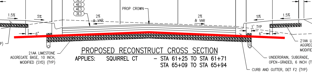
Track Grades
When performing paving we need to add a place outside the paved area for the machine to smoothly follow the road profile. This track grade needs to be included as a separate model to subgrade elevation.
An average horizontal distance is 5-feet. When building this, we must be careful with stepped subgrades and super elevation transitions. These complicate things and call for special procedures. The result must be a smooth extension of the roadbed, so the paver does not jump or make exaggerated corrections.
When paving is done, the work needs to be covered up and normal shoulder and grading slopes will need to be made. This requires a different model to show how things will look when finished. Any road job starts with templates that represent the finished work. When we get things to final condition, we can now do dial-downs for subgrades, edges, and slopes. Multiple models make things more difficult for the field. Make sure everybody is on the same page. The best way to accomplish this is to have one person in charge of loading machines and rovers.
Daylight Models
As I mentioned, we start with a complete model from catch to catch. This means we are intercepting the existing ground with the correct slopes and transitions. A different model will eventually go to the paving sub, but when we start with a complete model there is no doubt how the individual pieces will fit.
The most critical component are the driving lanes. Make sure all elements are correct and correspond to the plans. We see differences in COGO math with alignments all the time. It is up to the model builder to get things correct, even if the math seems a bit off. This could be an entire post on its own.
On roads with curbs, attention needs to be made to the base under the curb. Many plans are drawn with intricate steps and slope changes. You may find out later that “we just do it this way” simplifies the job. Check with the stake holders to confirm. We might make an intricate model that has to be redone and simplified based on local value engineering.
Side slopes are typically easy. You may find special fill materials being used for improving erosion resistance. Be careful of your trigonometry when calculating the actual depth of the material. This stuff is usually expensive, and you do not want to waste it.
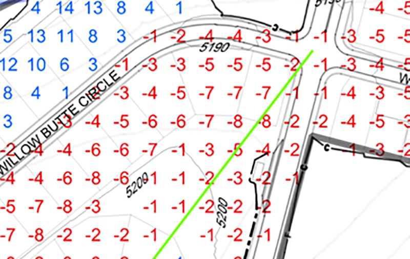
Slope Stake Reports
Whether it is for the field to use, or a requirement of the job, slope stakes can be a big help when used properly. The biggest advantage is the ability to use non-guided machinery to do most of the heavy lifting. When things get close, machine control can get it right on the money. Producing these reports is not difficult when using the software used to make the initial model. This is another reason we start with a complete daylight model. Slope stake reports are just a few mouse clicks.
For reporting options, we always default to what the contractor and surveyor on the job are used to. Remember, it is easy to customize reporting in the office and difficult to try and rethink an unfamiliar format in the field.
In the early days of machine control, we were lucky to have everything working at the same time. Hardware and firmware needed a lot of work and seemed to get worse with upgrades. Those of us who got past the tough times now have keen insight into how to trouble shoot hardware, firmware, and data models. When the bugs got worked out, we started to look ahead and really leverage the technology. In this installment, I will go over what we are able to do with data for subdivisions. Many of these ideas come from clients wanting to do more with their gear and trying to get the best from our modeling capabilities.
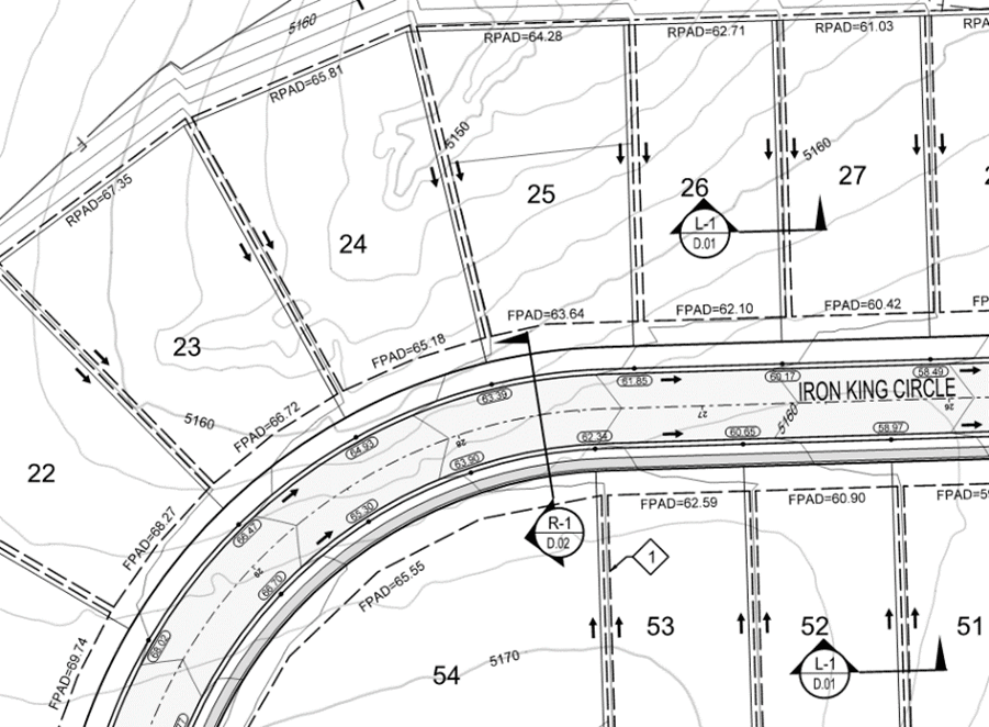
Basic Subdivision Models
It all starts with a model that represents the streets, pads, and common areas to required finish condition. By this I mean that depending on the scope, it may be street paving and curbs or rough grade if all they are doing is dirt.
The difficult thing about subdivisions is that we are working on a lot of corridors and intersections, and they all need to work together to make water do what we need for homeowners to drive safely. Nobody wants to scrape their spoiler on a steep dip or go airborne on a bump. These details should be sorted by the time the plans get to us but there can be issues that need addressing. We can catch issues during data production and let our client and the engineers know before a bad idea gets paved. Here are basic subdivision deliverables.
• Streets to finish, subgrade, or gut section (more on that later).
• Streets need to be done to plan/profile and template. We then drop them on plan view and clean the intersections.
• Pads to their finish grade condition. This may be flat, sloped or stepped for walk out basements.
• Common and retention areas to finish. We may also include a subgrade for retentions if there is a liner or filler material to go in. This could also be sod.
• Some large lot sites do not get graded pads. We usually do a 3:1 cut/fill slope to native so the custom home can grade as they see fit.
• Utilities are optional and with housing, there are a lot of connections. This is a great data tool to use in the field.
For a long time, we were doing some cool stuff with housing. After the 2008 crash, the market came to a speeding crawl causing many of the forward-thinking people in the field to pursue different areas, and some never got back to doing houses. When things started to bounce back around 2012, housing was new to many people. Yes, we are still moving dirt but some of the tricks we used in the past to make things faster were new to the fresh crop of housing contractors.
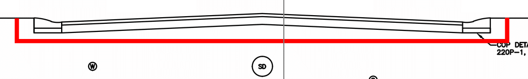
The Gut Section
Many times, we are asked to build several different models for the streets. With top of native and possibly subgrade surfaces, we also build gut section models. This allows the contractor to rough grade for streets leaving room for the utility spoils to be used in place to get the job to top of native.
The red line represents the gut section. After the utilities are installed, the remaining dirt will be used to get the job to top of native. Note there is subgrade as well as paving shown here. Using this approach reduces the movement of dirt as well as speeding up the process.
Haul Roads
When doing large cuts and fills on a site using scrapers or haul trucks, good smooth roads are beneficial. Here is how we look at and build haul roads.
• Look at cut/fill regions. Connect large cut to fill areas to make transfer easier.
• As much as possible, use existing streets and connect them with custom haul roads that connect to the design profile grades so you are building road subgrade at the same time you are hauling.
• Produce machine control models for the haul road/finish street combination.
• Grade these on a regular basis to optimize the speed of equipment and keep stated cycle times.
• The roads often run through areas that are to be restored native or park areas. Verify you can do a topo of the area for returning to previous after your work is done.
• Sometimes we build a road on existing ground conditions to start. As dirt is added/removed, the crews dial down/up to grade the road. We have done three or four iterations of the profile for big cut/fill jobs.
The reason for these proposed basic rules is that many jobs were looked at like a site. Regions made from large cut areas and moved to large fills. When you utilize the finished street alignments you get a head start on them as well as leaving most of the pads alone to be completed early so crews can stay busy.
Early Utilities
Installing underground utilities requires a bit of planning but has become a real time saver in the field. We are now working on sites that are expensive to build on because of the large amounts of required dirt moving. None of us want to dig more than necessary so I got an idea. Why not install underground utilities before all the fill is done? Apologies for the poor example but I just could not find a recent set of plans with huge fill.
• Let us assume the minimum cover for the lines is three feet.
• In large fill areas, there may be 20 feet of dirt that needs to go in.
• We run calculations on areas where the storm and/or sanitary have more than three feet of cover.
• We build a “utility base fill” model.
• This model gives you three feet of fill in the utility areas.
• You can now do minimal fill, trench, and place pipe.
• When complete, the fill goes on as usual with compacted lifts as required in the engineering reports.
This works for different projects, not just housing. When you encounter large fill areas, keep this in mind. When using multiple surface models, be sure everyone is on the correct page. Things can get out of control quickly when there are mixed messages in the field. This is where the field person responsible for loading machines and data collectors are required to be on top of things.