The Bell Helmet Company once had a magazine ad with the statement, “If you have a 5-dollar head, get a 5-dollar helmet.” Wise words when you think about protecting your brain. The interwebs have done a great service to us; we now have experts in every corner of the world. I admire some of them but do an eye roll with many. As one of the original innovators in the industry, I’m not pulling rank, I am speaking from experience. I just do not like to hear bad information being passed off as truth.
Regarding those who advertise low-cost data, I have but one thought: If your work was worth more, you would charge more. So many people are not invested in making a good product, but just making a product. I have spent my career working on delivering data in the fewest mouse clicks possible. We like to bill for work done efficiently by trained professionals who have been trained by experienced mentors familiar with a lot of different data issues. When the experience issue gets brushed aside as a “nothing burger” by more recent entrants to the data industry, one has to look at the actual time it takes to decode and properly set up a project.
Many times when inexpensive data gets built, it is just converting a surface built by the engineer at some point in the design. This is usually done to get a rough dirt number so that some quantities can be put on the plans. When doing a takeoff and I was close to the engineer’s numbers, I went through things again. Those quantities are usually never close. The surface is not only a few changes behind the plans, it lacks the detail for successful grading. Here is why proper data takes a bit of time.
Initial Data Files
We receive the plans and CAD in addition to a work order for the job. We often find that the plans and CAD are a mismatch. Not a big deal. Just find out which of the two is correct, get the current file and we are good to go. For every job we do, the files get touched by no fewer than three software platforms. It is not cheap to have all that horsepower, but we can do a more efficient, competitively priced job with them. We need to read the plans and relevant specifications to insulate our client from issues. We want no surprises. Notes on the job guide our work, then we start building.
The Big Picture
I will use a sample project to give you an idea of what good data, coupled with 25 years of experience, looks like. The data engineer working on the job has a deep bench of talent to call on for advice. A great advantage that goes a long way in securing a good job for our clients. Here are the basics:;
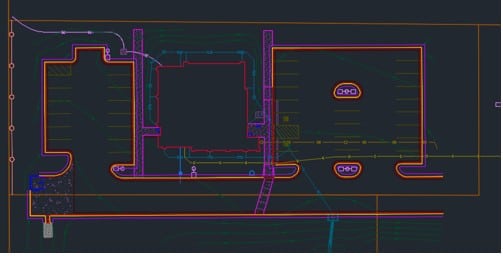
The entire job consists of a building with a basement, parking for 200 vehicles, and a long entrance road.
There is detailed landscaping along with a lot of drainage work, (wet part of the country).
We also need to build an initial water management surface, as all the water needs to stay on the project. Watershed pollution prevention.
Initial CAD Work
We have detail sheets that we populate for our clients. Surface density, line colors, file types, and delivery method are a few of the things that make a job easier for our clients’ field crews. As a former field hand, I like to be in their corner and do everything possible for them. Five minutes of work in our office on the computer saves 30 minutes balled up in the cab of a work truck, trying to change something. Here is the process.
Civil 3D files can be feature rich. That is good news for somebody doing poor work and just converting a surface. In our world, that is something we delete to make the file smaller.
Lines have become critical. A grade checker will want a 3- foot back of curb 3D line to set string or hanging forms. A blade hand wants to snap on an edge of pavement line to shift the blade 2 feet behind the curb for slip former access. All of these lines need to be in the correct direction, void of any overlaps and breaks. That takes time.
With the paper plans ruling, we need to confirm that the job looks like the CAD; this can be time- consuming and frustrating. The best that one can hope for is a spot check with budget data work.
In the early days, we worried about file sizes, but not so much anymore. It still makes sense to show only the lines necessary to complete the work. Text needs to be simple and in a format that does not steal bandwidth from a controller.
Surface Components
Since the beginning of the data business, we have used the same elements for building data. Each of these must be carefully created and work with the other parts.
2D Lines
Contour lines are really 3D lines as they are elevated. But because it is all the same elevation, we call them 2D lines. How those lines are produced is something the model builder will find out if they are doing their job.
Sometimes points are placed on the surface and contours are produced later.
Contours can be drawn by hand to show intent. That means you cannot use them on the surface, but they are nice to look at.
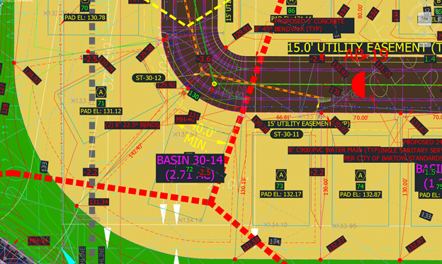
Contours are made first to show slopes and sheeting water, usually in a parking lot. They are interrupted later for islands and other features.
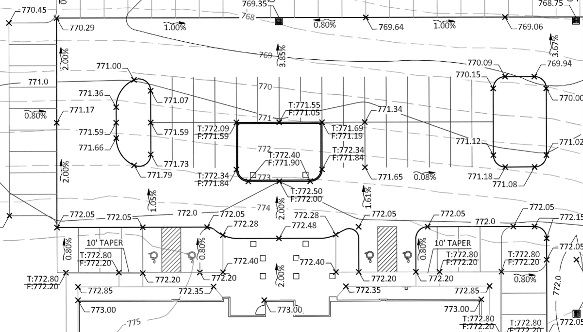
In our example shown above, the contours were drawn in later to show the general slope of the parking lot. The slope arrows provide some faint clues on how the water is moving. This one took some time to get right.
3D Lines
When doing curb, the elevation of a line changes. We first need to plug in the numbers from the plans, then fix issues that are obvious.
If there are things that do not make sense, we need to run a request up the ladder and get more information.
In our sample project, the slopes in the ADA parking areas are out of spec. This is not an issue; we check the percentages and make them right. If they do not fit, we need to talk to someone. A quick once- over of an engineer’s surface will not catch these small details.
There are a lot of things we can do with these lines. Offset the flow line to get top back of curb, even extend that line for staking. This requires us to create lines, which cannot be done from a surface found in the original CAD.
Points and breaklines
I have always used points to create an absolute elevation. Think of the rim of a storm grate.
Points are used by our clients to layout improvements.
Points are useful for curb radius points as well as footings and building corners.
We will do layout of light poles, playground equipment, electrical lines, and SES pads. The list is long.
Breaklines are used to make a surface respond the way you want it to. Triangle linking is indiscriminate and these lines make features look like the design. This could be from a simple ditch to parking lot flow lines.
They become the final tool to get things looking right. They are a necessary and sometimes frustrating tool. Too many breaklines and the surface is strained, too few and details get lost.
Summary
In order to use a surface made by someone else, the above issues would need to be addressed. It takes longer to take things apart and put them back instead of doing it right the first time. Cheap data uses information that is not correct. A few checks and it lands on your site. Instead of a surface you have a minefield, not knowing where the bad spots are. There is still a culture of “fix it in the field.”. This does happen when provided with too little information, but it is the rule when dealing with marginal work from less -experienced model builders.
I, in no way, am faulting engineers for this. Any surface made by them is for a different purpose. It is the job of the model builder to get inside the plans and understand the site from a singular point of view. Will it perform as intended? Years ago, I wrote an article in Machine Control Online Magazine. The title was “You Pay Us to be Nervous.” You just cannot do a good job in a couple hours.
A change came about at the beginning of the 2023 year that can have an impact on you and the survey work you do in the office and the field. The new rule:
The United States will retire the use of the US Survey Foot and unilaterally adopt the International Foot as the standard of survey measurement.
Until now, only 5 states have used the International Foot. The US Foot is a ratio and is not an exact conversion like the International. From a geodetic standpoint, this new standard will improve accuracy. The International Foot is 2 feet per million feet longer than the US Foot. This will allow you to look at the coordinates of your location instead of focusing on the size of your job.
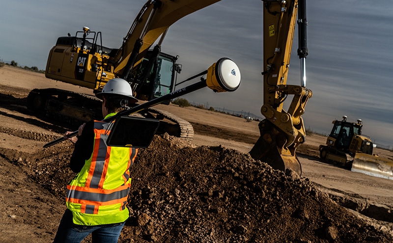
Learn how the International Foot can affect your survey work and how to easily adopt the new standard in the field and at the office with best practices.
See the International Foot in Action
When using state plane coordinates, we are often 2-4 million feet in the coordinates of our work. If the job is produced on one unit type, then changed to the other, the job has now shifted 2 feet per million feet in both the north and east grid directions with non-affected elevations.
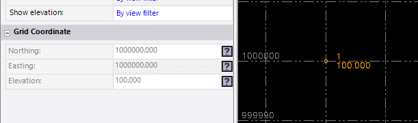
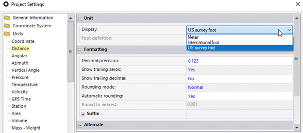
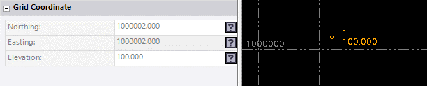
To illustrate further, here is a job started with a US Survey Feet point drawn at N1,000,000 E1,000,000.
Now, let’s update the point drawn in US Survey feet by changing the units:
If the survey standard unit changes to the International Foot, you can see the 2-foot shift in the entire job with updated coordinate points.
In the past when the US failed to adopt the metric system, plans were drawn in a metric that was worked on for ten years after an idea was abandoned. Similar outcomes are expected to happen with this new transition as well. Realizing the big impact that changing units can have on your jobsite, it is important to have best practices put into place so that you are set up for success and rework can be prevented.
Best Practices Moving Forward
Units should be listed within the first few pages of the job plans, so the next steps are identified. Over the next few years, while jobsites are being acclimated, here are some action items to keep your work updated and ready to transition.
It is imperative that all parties use the same units. The job does not necessarily need to shift right away. If ALL parties are staying with US Feet, you can localize and continue.
Do not rely on Google Earth to verify your current unit’s accuracy. It’s not a very reliable resource.
Have control pointson the jobas you are building the model. It is the definitive test as to the correct units. Based on the previous example, if the control point was 1,000,000/1,000,000 you would know you were measuring in US Feet. As long as everybody stays there, you can proceed.
Problems can arise when somebody changes units either in the office or the field. So, taking the correct steps to manage the file and jobsite correctly between both places is imperative. Here are two checklists for teams in both places to reference:
In the Office
Verify units by having control points before sending the job to the field.
If you make the job in one unit type and switch to the other, make sure you export all the job files after you have shifted the job.
Add a suffix to the job file. Now it has job name-date-units. An Example would be QuickTrip3385 010123 IFT (or USFT).
At some point in the model-building process, send an email and receive a response including the project units.
Software types behave differently. Some will shift coordinates and not present a warning while others will. Know your software.
Final review needs to include the control points. Make sure the coordinates and points make it to the field for verification.
In the Field
Know your units and do not change them between data collectors and machines.
Calibrate the job with the units being used by everyone. The coordinates of your control points must match the surveyor.
The elevation does not change if the coordinates are shifted, no need to worry about that.
Upon starting for the day, check in to a known point for verification. This can be a control point or one you set yesterday before stopping for the day for ease of access.
If you are unsure about the new survey measurement standard or 3D modeling for machine control, reach out to TOPS and we’ll be happy to help.
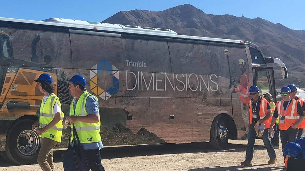
Over the years, I have received many calls and questions from those who have been on the fence about attending the Trimble Dimensions Conference. Well aware of all the planning and costs for an event like this, I’ve listed out considerations that I think are important in making a qualified decision on how you can make the most at a conference like this.
Spoiler alert, I’ll give the answer first, then explain. As a major data engineering firm, we require the regular use of Civil 3D. For those of you that provide data for your own company, you can usually find workarounds to save money. Once you have the budget to acquire Civil 3D, you’ll have to learn how to effectively use the program.
Personally, I do not know the program and never really liked it that much. It is not very intuitive and took a long time to learn mostly because the classes were taught by geeky users who were thrilled at how many mundane things could be done with the software instead of doing work. But that is a discussion for another day. The most common task I would perform would be the conversion of a MicroStation surface to something we could use in other programs. I got some training, and everything worked great for a few months. Then the software was upgraded, and my cheat sheet was worthless. Back to the drawing board. I had to perform other tasks as well in MicroStation that had varying degrees of success with upgrades.
What are the benefits and risks of investing in Civil 3D?
Remember, you may know how to do something today, but an upgrade may change that routine. Here are some things to keep in mind.
To license a seat of Civil 3D, you are looking at about $2,500.00 per year.
You can rent the program with tokens. More on that later.
If you do not know what to do, training will be required.
It is a frustrating program to use and difficult to learn a few commands without being familiar with the structure of commands and processes.
It takes at least a week or two of training to get used to the program to perform your desired application.
Training may not be targeted to your needs and could require you to learn a lot of things you will never use.
CAD Tokens
The use of tokens for Autodesk Products is a new option to purchasing software. I like the concept because I use Revit on a sporadic basis and cannot justify a yearly subscription. A look into the cost of Civil 3D tokens resulted in the following data.
Tokens are $3.00 each
Civil 3D costs 9 tokens ($27.00) per 24-hour period
Shut down the program during the 24-hour period and the tokens are considered spent for the session (Pro Tip).
If you are comfortable using Civil 3D to perform the required tasks, then this is a good deal. If you are new to the program, or a few releases behind, it will be better to license a seat and access the program on a regular basis for training and use. It will be much less frustrating.
That brings up the issue of training. The wonderful thing about Civil 3D, and all Autodesk products, is the wealth of training resources on the web. Do some research, as the quality varies widely, and certain You Tube channels and websites have different areas they cover. I will start with a search on what I am looking for and drill down a couple of rabbit holes until I get to the information I need.
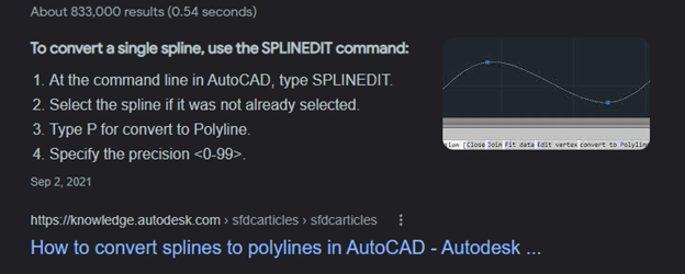
Let us say I want to get rid of splines in a drawing. They make a mess in non-CAD programs, and it is best to convert them in CAD. A quick search gave me a tip from the Autodesk site. Quick and easy.
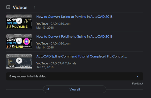
I will also save video tutorials from various sites, and then bookmark those sites to reference as needed.
These are obviously not crazy deep dive commands and once you go through them a few times you will remember how to use them. You can also refer to my article on “Seldom Used Commands” that shows how to build a log and cheat sheet to speed up the process.
After you have convinced yourself you cannot live without Civil 3D, or you are trying to get somebody else to buy it, what things can you do with it that cannot be done in non-CAD programs?
I must first warn you that non-CAD vendors will tell you that they can import CAD elements and that is not always the case. When all you have is a hammer, every problem looks like a nail. I regularly work on CAD files for our staff and extract items that come in messed up. You sort of do not know what you are missing with importing tools used for outside files. To test that idea, verify the import looks just like the PDF plans, there will usually be some items missing or corrupted. This is not always a bad thing but miss one good layer of spot elevations and your frustration will make you long for a seat of Civil 3D. Go and spend a few tokens and make it happen.
What Can You Do With CAD?
Here are a few of the things you can do well in CAD that may not work as good on other platforms.
Splines: I mentioned this before, but they can cause real issues if not converted to polylines.
Blocks: CAD blocks do not always import well and sometimes not at all. You can Burst or Explode the blocks.
Non-CAD programs can only Explode if they import the blocks. The Burst or explode is a whole article on its own, research it if you are interested.
Alignments: Civil 3D corridors are feature rich elements that we do not use. Our clients pay us to make the corridors in the non-CAD software they use. We can, however, extract the alignments and use them after checking their accuracy. It’s a great tool for long roads and rails.
Surfaces: A lot of existing ground surfaces are Civil 3D surfaces and do not import well into some non-CAD programs. A little work in CAD makes things easier.
Text: M-Text can cause issues on import due to the sizing attribute it gets in CAD. Changing settings of these will make them work better.
Leaders: Sometimes not a big deal but dense data has a lot of arrows and knowing where text points are can help. The problem can be the leaders are dynamic in CAD and will not appear on import.
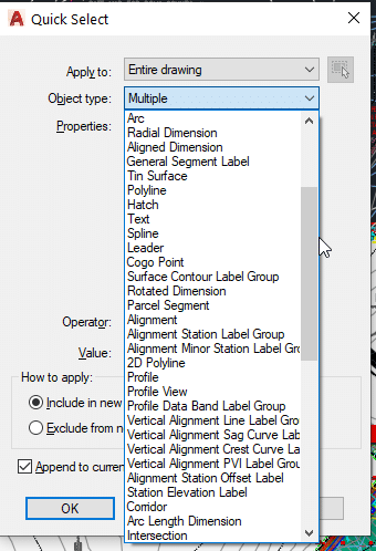
This is a screenshot of the dropdown menu for Quick Select. These items should be made basic CAD elements if possible to improve the import of the data and for faster refresh rates on the screen.
There are more examples I deal with daily, but these are just a few of the most common ones with easy resolves. For help on your next big project, don’t hesitate to give us a call at (623) 323-8441! Our expert engineering staff is here for you.
The last thing any of us want is a job done wrong due to lack of communication. In a perfect world, the team is on the same page and works out issues at the data stage. Unfortunately, about 20% of our jobs go this way. The industry average is about 5%. My team gets all parties talking at the front of a job due to experience and repeatedly work with firms who understand we are there to make things go as smoothly as possible.
Engineering firms are not to blame. Their reason for not being cooperative may be they are too busy to have a nice long talk about what you found wrong with their job. With proper coordination and your experience as a data engineer, doors will open and there will be better, quicker interaction with designers. Here is how to work things out.
Data Production
We need a starting point to get things rolling. In our case, it is the building of the model provided after the contractor has won the job. If everything is scheduled correctly, the data is received before field work is ready to start, and there is time for building and review. While building the model, we are looking for a lot of different things.
Overall quality of the plans.
With experience, you can tell when things were thoughtfully prepared or just kicked out the door.
Obvious issues with elevations, COGO, and drainage.
A few spot grades that are not correct is normal. We will fix them and report it to the contractor.
The COGO, (Coordinate Geometry) is another thing. When the layout of a site is not consistent from page to page, we need to let people know. A building must fit, cars need to park, and water needs to be managed. If the site permit calculations call for 165 parking spots and the grading sheet only shows 140, we need to alert the team.
Laws regarding the handling of onsite storm water have changed and become more restrictive. Most sites need to contain and properly drain runoff. Know the rules and verify the cubic footage of water as compared to the plans. If there is a difference, everybody will thank you for not letting the wheels fall off that wagon.
Experience with the engineer and contractor. When working with known entities, communication is easier. We know who to email and where to get results. With new people in the mix, it is best to get acquainted quickly and establish your main contacts.
Share the model with everyone. At the start of the project, try and get the right person with the contractor and engineer in the email loop.
When you have a feel for how good things are and who is committed to making things happen, you are now on course to get things taken care of.
Dealing with Issues
There will be things that need to be changed for the project to work, at least on the screen. Sometimes we see an issue that does not look right, and we bring it to the attention of the contractor and engineer only to find out they wanted it that way. Usually, it needs to be changed. How you present the issue is more than half the battle.
Never bring up a problem without offering a solution. There are two reasons for this:
First, everybody will know you are familiar with the project.
Second, nobody wants to figure things out. We are the professionals in making a surface, we should have some clue for success.
Put together a well thought out email to the group.
This means that when they read the email, they should have no questions.
Do not send out something that says, “call me.” Yes, there are times on complex projects that some type of discussion is important, but for the other 95% of the time, be clear and complete in this communication.
Always put some deadline on the request but don’t go around wanting everything in an hour.
Pick your battles and leave as much time as possible but be sure to put a limit on it. If you do not get results, they should know you will go ahead and change things or just leave that section out of the model. That will get you answers.
Don’t sweat the small stuff.
A fat-fingered elevation is no cause for a Zoom call. Just make sure you note the changes made in a communication to the core group.
Everybody is busy. The engineers’ process for dealing with the problem you present may take a meeting on their part.
The message here is to note issues early on so the rest of the project can move along while the details are worked out.
Helping Surveyors
When working on a project, we want everybody to get a copy of our data. It is always better to have several eyes on your work so there are no surprises down the road. In over 80% percent of our jobs, we will provide working files to the surveyors to help them with their portion of the job. This covers several factors:
The surveyor can look at the data and let us know if they feel changes are in order.
We are already producing a lot of the information needed for layout, so we can add points or a subgrade file for the survey crews to get to work.
The survey bill to the contractor will be reduced. No surveyor wants to be stuck in the office doing calculations to send to the field.
It has taken a lot of years to get to the point where we have the trust of most of the large engineering and surveying firms in the country. Now that they are familiar with our work and competence, we are welcomed into a job. If this is your first time with a group, proceed slowly and earn their trust to prove your capable of providing accurate information.
Take Off Professionals is always open to sharing our experience and knowledge. Contact us online for assistance with dirt takeoffs, 3D models and more, or call us today at (623) 323-8441.
One of my superpowers, (maybe my only one) is the ability to find and know how to use obscure commands. I have an advantage in that I am constantly helping engineers on various projects. They may want to streamline a process or be stumped on how to get through an issue. Having a variety of projects to work on keeps me in front of new commands as well as old favorites.
You never really get to know all the commands in a program, few of us DO everything a software program is capable of. An issue presents itself when you’re required to step outside your daily routine. This can involve a process you barely learned about in training, requiring you to do something difficult, just to forget it until you need to perform the process again.
How do you find a command you never use and do just enough to get the process done and back to work? I will go through how I locate and proficiently use those seldom used commands.
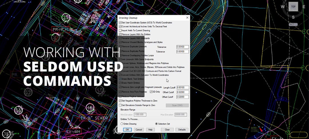
For this offering, I will be looking through Carlson Software on AutoCAD Civil 3D. The program is mature and there are a lot of commands that are deep in menus or even only accessible by command line. Trimble Business Center, being a bit newer, isn’t as complex. The fact that it is module based will limit your access to commands outside your normal routine. The challenge comes when you take on new responsibilities, add modules and start hopping back and forth.
Identify Commands
How many times have you encountered an issue that could be solved with a command you used two years ago? You forget the name and don’t really want to go through the entire command list to find it. I suggest this approach. When you need to find a command, take a step back and put yourself in learning mode. If you try and grab and go with a command, you may not get it right and the next time you need it, the process begins again.
To make sure this never happens, do some work to make things easier the next time. There is a way in Carlson to make points at the intersections of lines. I will dig until I find it but to save time, I will make a “command sheet.” I’ve listed the items I put on the sheet below. They can all go into a Word document so you can search command words to make things easier. As I go through the process for getting familiar with a command, you can choose the elements you want to put into your version of a command sheet.
Command Name
Name the software uses for the command.
Add keywords to describe what it does and how to apply it.
Prior and possible uses for the command.
Tip: When you are in learning mode, watch how others are using the command.
Command Location
Both menu and command line descriptions.
A walk through of how the command works. Add screen shots as well as dialog to make it clear. Remember, you will not look at this for months, in addition, it will be shared with others in the office, and it needs to be self-explanatory. I sure do not want to field a call about a command I do not know well.
For this example, I will drill down into a Carlson command.
Command Name: Create Points from Entities
Keywords: Points, create points, points from lines, intersections, radius points, extra points
With these basics I can go back and search my document to locate the command for future use. At this point, I want to work with the command to get familiar with it so I can do some documentation.
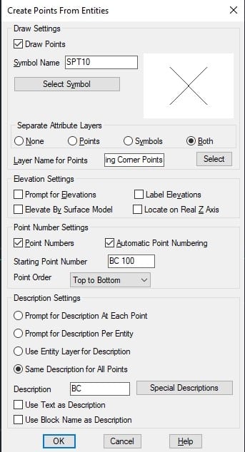
Dialog Box Notes
Verify symbol and layer for draw points.
Always separate attribute layers to keep screen cleaner.
Check points elevated by the surface.
Always locate on Z axis.
Do automatic point numbering, try, and use alpha-numeric for clarification in the model.
Point order can be left to right or start at the top or bottom.
Description settings if needed.
With these parameters listed and noted, you will save time the next time you use the command and get things looking the way you want. Here is the dialog box with the desired information and appropriate settings. These are 2D points so they will not be located in 3D. Once the dialog box is populated the way you want, you can move to the next.
The dialog box can get you into trouble. Any time you are using a command, be sure to save the project first before shutting down the program. The reason is it can cause issues like you may get points where you do not need them as well as way too many points. The points in Carlson go to a coordinate file and would need to be removed even if you close or undo the command. Proceed with care.
Consider accessing the help files as they can actually have useful information. Here is part of the Help instructions for this command.
This command will create Carlson points on selected entities. The points are stored in the current coordinate (.CRD) file and drawn on the screen. For arcs and polylines with arc segments, points are created at the radius points of the arcs as well as the PC and PT.
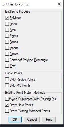
In the first options dialog, there are settings for the point attributes. To have points obtain their elevation from the selected entities, unselect the Prompt for Elevations toggle and select the Locate on Real Z Axis toggle. After you have specified the point options, a secondary dialog appears which allows you to specify the entity types to process. The Point Order setting controls the sequence of the new point numbers to be in the order of selection or in a direction like left to right. Under the Description Settings, Prompt for Description At Each Point will prompt you at the command line for a description for each individual point. Prompt Per Entity will ask you for a description per each highlighted entity. Use Entity Layer for Description will assign the layer name to the description. When Entity Layer for Description is checked, the layer name of the entity will be used as the description for the created point. Same Description For All Points will prompt you for a single description for all points. The Use Text as Description applies to points from Text entities where the description is set to the text string. The Use Block Name as Description applies to points from Insert entities and the program sets the point description to the block name.
The second options dialog has processing settings. When Avoid Duplicates with Existing Pts is checked, this routine will not create a point if a point with the same coordinates already exists in the current coordinate (.CRD) file. The Draw New Points option creates point entities in the drawing. Otherwise, the new points are only stored to the coordinate file. The Draw Existing Matched Points option applies to the Avoid Duplicates option for the case when a duplicate is found in the coordinate file and not yet drawn.
That is a lot of information that will come in handy. I will also usually copy and paste the help dialog into my command sheet if nothing else to have more searchable words. I also save the file as a pdf and use Bluebeam to search; it does a great job and notes where the text is as well as words around it for context.
Other Considerations for Seldom Used Commands
This is to be shared with others in your group. I suggest creating a document intended to be shared by everyone.
Do not use this as a substitute for training. This is more of an advanced search tool with written reminders of a command you learned how to use some time ago. I see too many mistakes when a command is executed, and problems arise when something goes wrong, and the operator does not understand.
Many of these commands can be used for another purpose than intended. This Create Points From Entities command can be used to create layout points for staking curbs and buildings. Most people use it to densify a model or elevate point cloud data with local feature lines now correctly elevated.
The keyword section can contain random entries that can bring the command back to memory. For example, I have an entry “command C Lawson showed me at dinner.” When the file gets over 100 commands, you sometimes need to stretch the box.
Stumped on a project? Need extra hands to stay on schedule? We can help! Contact us and find out about how our expert engineers can assist you on your next takeoff or modeling project today!
Creating an exact earthwork estimate is an essential first step to many takeoffs. You want a bid that accurately reflects the cost of labor and materials so you can get the project fee you deserve and minimize financial risks. At Take-off Professionals, our experienced team of engineers creates precise earthwork estimates based on your designs.
This post will explain what earthwork estimates are and the three methods we can use to create them.
Fundamentals of Earthworks: Excavation and Embankment
Earthwork is the engineering process of moving, removing or adding soil, rock or other materials to change a specific location’s topography. To create a 3D earthwork calculation, compare the location’s current topography with the contractor’s proposed design. The process of creating an accurate earthwork estimation consists of calculating how much material the contractor will need to add — or fill — and take away — or cut.
Cutting is removing material from the site, and filling refers to adding material. Both are crucial for creating the topography reflected in the contractor’s design. Engineers will calculate the cut and fill quantities to reach a mass balance and use that mass balance to provide an accurate earthwork estimate.
Elevate Your Project Efficiency with Accurate Earthwork Estimates
At TOPS, we deliver precise earthwork estimates and essential 3D data to drive your project forward. Our models aid in enhancing project efficiency and accuracy, regardless of project size, enabling successful completion.
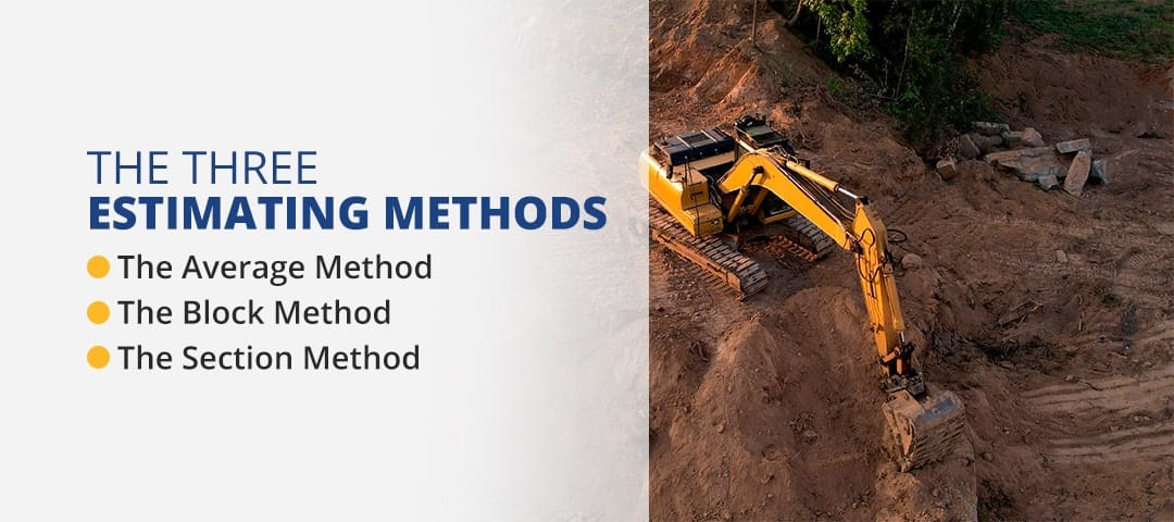
There are three main estimating methods that engineers can use when creating 3D data for earthwork in construction. These methods calculate the dirt and material quantities required while providing mass haul analysis for the construction site. However, some are more accurate than others.
Method One: The Average End-Area Method
We typically use the average method for smaller projects that require us to ascertain the levels at all grid points. Because this method is the simplest of the three, we can only use it when a project requires either filling or cutting. The average method provides inaccurate estimates if you use it for projects that use both cutting and filling.
Method Two: The Grid-Cell or Block Method
Our team uses the block method — also called the division of square method — to determine volume for medium-sized projects that require leveling. The block method is more straightforward than the section method and more accurate than the average method. You can expect some margin of error when using the block method on projects involving both filling and cutting, but much less than the average method.
Method Three: The Cross-Section Method
The section method is the most complex and precise way to calculate an earthwork estimate. We use this technique when working on large-scale projects, such as dams, railway systems and roads. Although the section method requires many steps and more complicated calculations, it’s the best method to ensure a precise estimate that will save you money.
Precision Earthwork Estimates with Take-Off Professionals
Our team of full-time engineers is on hand to provide you with precise earthwork estimates and essential 3D data. Contact us to learn more about our products or request a quote for our earthwork services.